Transformers Articles:
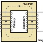
How does a Transformer Work and Purpose of Transformer: How does a Transformer Work – A Transformer Circuit is a static device comprising coils coupled through a magnetic medium connecting two ports at different voltage levels. In an electric system allowing the … (Read More)
Construction of Transformer and types of transformer: Construction of Transformer is intimately related to the purpose for which these are to be used; winding voltage, current rating and operating frequencies. The construction has to ensure efficient removal of heat from the … (Read More)
Transformer Cooling System: Transformer Cooling System (Large Units) – Basically, there are two seats of losses in a transformer namely: Core, where eddy current and hysteresis losses occur (caused by alternating density). Windings (primary and secondary) where I2R or copper loss occurs because … (Read More)
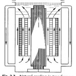
Natural Cooling System in Transformer: Natural Cooling System in Transformer – Smaller size transformers are immersed in a tank containing transformer oil. The oil surrounding the core and windings gets heated, expands and moves upwards. It then flows downwards by the … (Read More)

Forced Cooling in Transformer: Forced Cooling in Transformer – For transformer sizes beyond 5 MVA additional cooling would be needed which is achieved by supplementing the tank surface by a separate radiator in which oil is circulated by means of a … (Read More)
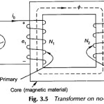
Phasor Diagram of Transformer on No Load: Figure 3.5 shows the schematic diagram of a Phasor Diagram of Transformer on No Load with Two Winding, i.e. the secondary terminals are open while the primary is connected to a source of constant … (Read More)
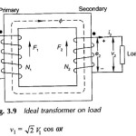
Ideal Transformer on Load: In order to visualize the effect of flow of secondary current in a transformer, certain idealizing assumptions will be made which are close approximations for a practical transformer. A transformer possessing these ideal properties is hypothetical (has … (Read More)
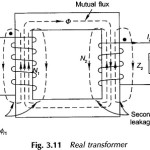
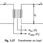
Real Transformer On Load Condition | Equivalent Circuit: Figure 3.11 shows a Real Transformer On Load Condition. Both the primary and secondary have finite resistances R1 and R2 which are uniformly spread throughout the winding; these give rise to associated copper … (Read More)
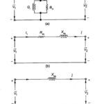
Approximate Equivalent Circuit of Transformer: Approximate Equivalent Circuit of Transformer – In constant frequency (50 Hz) power transformers, approximate forms of the exact T-circuit equivalent of the transformer are commonly used. With reference to Fig. 3.14(c), it is immediately observed that … (Read More)
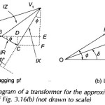
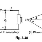
Phasor Diagram of Transformer: For the approximate equivalent circuit of Phasor Diagram of Transformer is shown in Fig. 3.16(b) The phasor diagram corresponding to this equation is drawn in Fig. 3.17(a) for the lagging power factor (phase angle Φ between V2 and I) … (Read More)
Transformer Nameplate Rating: Transformer Nameplate Rating Details – The voltage ratio is specified as V1 (rated)/V2 (rated). It means that when voltage V1 (rated) is applied to the primary, the secondary voltage on full load at specified pf is V2 (rated). The … (Read More)
Different types of losses in transformer: The transformer has no moving parts so that its efficiency is much higher than that of rotating machines. Different types of losses in transformer are enumerated below: Core Loss in a Transformer: These are hysteresis and eddy-current … (Read More)
Transformer Testing Methods: Two chief difficulties which do not warrant the Transformer Testing Methods by direct load test are: Large amount of energy has to be wasted in such a test, It is a stupendous (impossible for large transformers) task to arrange a … (Read More)
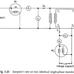
Sumpner Test of Transformer: While OC and SC tests on a transformer yield its equivalent circuit parameters, these cannot be used for the ‘heat run’ test wherein the purpose is to determine the steady temperature rise if the transformer was fully … (Read More)
Per Unit System: While carrying out the analysis of electrical machines (or electrical machine systems), it is usual to express voltage, current, VA and impedance in Per Unit System (or percentage) of the base or reference values of these quantities. The … (Read More)
Transformer Efficiency Formula: Power and distribution transformers are designed to operate under conditions of constant rms voltage and frequency and so the efficiency and voltage regulation are of prime importance. Transformer Efficiency Formula is the rated capacity of a transformer is … (Read More)
Voltage Regulation Formula of Transformer: Voltage Regulation Formula – Constant voltage is the requirement of most domestic, commercial and industrial loads. It is, therefore, necessary that the output voltage of a transformer must stay within narrow limits as the load and … (Read More)
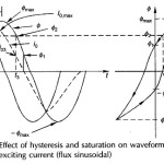
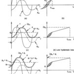
Excitation Phenomenon in Transformer: It was stated already that the no-load current in a transformer is nonsinusoidal. The basic cause for this Excitation Phenomenon in Transformer, which lies in Transformer Hysteresis and Saturation nonlinearities of the core material, will now be … (Read More)
Switching Transients in Transformer | Transformer Inrush Current: Switching Transients in Transformer – In the earlier discussion earlier steady-state operation was assumed so that v1 and Φ are both sinusoidal, Φ lagging v1 by 90° as shown once again in Fig. … (Read More)
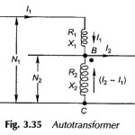
Autotransformer | Definition | Use of Auto transformer: So far two-winding transformers have been discussed wherein the windings are electrically isolated. When the primary and secondary windings are electrically connected so that a part of the winding is common to the … (Read More)
Variable Frequency Transformer | Application: So far we have considered transformers which operate at fixed frequency (50 Hz). Their purpose is to transform electric power from one voltage level to another; their performance measures being high efficiency and low voltage regulation. … (Read More)
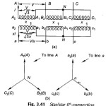
Three Phase Transformer Connections: In generation, transformation, transmission and utilization of electric energy it can be shown that it is economical to use the three-phase system rather than the single-phase. For Three Phase Transformer Connections, three single-phase transformers are needed. Two … (Read More)
Choice of Transformer Connection Diagram: The different choice of Transformer Connection Diagram are namely, Star/star: This is economical for small HV transformers as it minimizes the turns/phase and winding insulation. A neutral connection is possible. However, the Y/Y connection is rarely used because … (Read More)
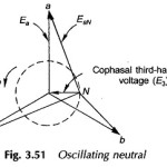
Three phase Transformer Bank of Single phase Transformers: The different Three phase Transformer Bank of Single phase Transformers are namely, Delta/delta connection: The supply voltage provides only sinusoidal magnetizing current so that core flux is flat-topped; but the third-harmonic emfs induced (cophasal) cause … (Read More)
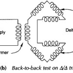
Back to Back Test of Transformer: The Back to Back Test of Transformer which consists of two parts namely, Back to Back Test on Three Phase Transformer Back to Back Test on Delta/Delta Transformers 1. Back to Back Test on Three Phase Transformers: Fig. 3.52(a) … (Read More)
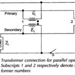
Parallel Operation of Transformer: When the load outgrows the capacity of an existing transformer, it may be economical to install another one in parallel with it rather than replacing it with a single larger unit. Also, sometimes in a new installation, … (Read More)
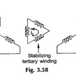
Three Winding Transformer: Three Winding Transformer may be built with a third winding, called the tertiary, in addition to the primary and secondary. Various purposes which dictate the use of a tertiary winding are enumerated below: To supply the substation auxiliaries at … (Read More)
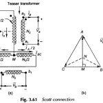
Phase Conversion in Transformer: Three Phase to Two Phase Conversion Transformer (Scott-T transformer or Scott Connection): Phase conversion from three to two phase is needed in special cases, such as in supplying 2-phase electric arc furnaces. The concept of 3/2-phase conversion follows from … (Read More)
Tap Changing Transformer | Off Load Tap Changer |On Load Tap Changing: Tap Changing Transformer -Voltage variation in power systems is a normal phenomenon owing to the rapid growth of industries and distribution network. System voltage control is therefore essential for: Adjustment … (Read More)
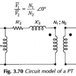
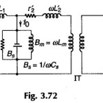
Current transformer and Potential transformer: These Current transformer and Potential transformer are designed to meet the specific need of measurement and instrumentation systems, which accept voltages in the range of 0-120 V and currents upto 5 A. Power system voltages can … (Read More)
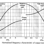
Audio Frequency Transformer: Audio Frequency Transformer is used at the output stage of Audio Frequency electronic amplifier for matching the load to the output impedance of the power amplifier stage. Here the load is fixed but the frequency is variable over … (Read More)