Torque Speed Characteristics of Induction Motor:
From Eq. 1.27 it can be observed that the maximum torque is independent of rotor resistance. However, the slip at which the maximum torque occurs changes with rotor resistance. When the rotor resistance is increased, so is the slip for maximum torque, and the stable operating slip range of the motor increases. Typical Torque Speed Characteristics of Induction Motor for different values of rotor resistance are shown in Fig. 1.22. From the figure it is seen that the starting torque can be increased by increasing the rotor resistance. The maximum torque occurs at starting if the rotor resistance is increased to a value.
![]()
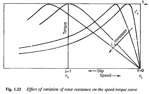
If the stator impedance is neglected the rotor resistance needs to be increased to a value equal to the rotor leakage reactance. If the rotor resistance is increased beyond this value the starting torque decreases. The breakdown torque occurs at slips greater than one (in the braking region). The starting current decreases and the starting power factor is better at increased’ values of rotor resistances. The full load slip changes, facilitating speed control in a limited range when the rotor resistance is varied. However, efficiency is impaired at high rotor resistances due to increased losses. Rotor heating is present in an inherently high-resistance rotor.
In short, the starting performance of the motor is improved with large rotor resistances while the running performance is impaired. To get the advantages of a high rotor resistance at starting, an additional resistance is connected in the rotor circuit of the wound rotor induction motor and slowly cut off as the rotor accelerates. At rated speed the motor operates on its natural characteristic. The connections are shown in Fig. 1.23(b).
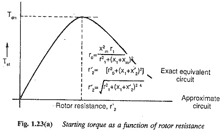
However, connecting an additional resistance is not possible in squirrel cage motors. Special rotor constructions, such as double cage and deep bar rotors are employed. At starting, due to high rotor frequency the current distributes in the outer cage of a double cage rutor or in the top portion of the bar in the case of a deep bar rotor. The effect of high resistance is thus achieved. As the motor speeds up, the rotor frequency decreases and the current distributes in both the cages of the double cage rotor or in the complete bar in the deep bar rotor. The effective resistance is small and running performance is improved. Typical torque-speed curves are shown in Fig. 1.23.
Effect of Voltage Variation in Induction Motor:
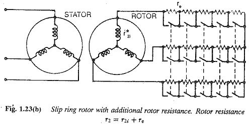
The speed-torque characteristic of an induction motor can be modified by Effect of Voltage Variation in Induction Motor. Typical Torque Speed Characteristics of Induction Motor when supplied from variable voltage at rated frequency are given in Fig. 1.24(a). They are based on the fact that the induction motor torque (at a given slip) varies as the square of the voltage. The slip for maximum torque is independent of voltage. The full load torque occurs at different slips when the voltage is varied. This renders the speed control of induction motors feasible over a limited range by supply voltage variation. However, the torque capability of the motor decreases at low voltages, because of reduction in the air gap flux. The power factor decreases. The motor draws heavy currents to develop a given torque at low voltages. The current drawn at different voltages is shown in Fig. 1.24(a), along with the torque developed at rated current at different voltages.
Figure 1.24(b) shows the advantages of high resistance in the rotor when the applied voltage is varied to modify the speed-torque characteristic. Besides increasing the range of speed control, the current drawn by the motor at low voltages can be limited by a proper choice of rotor resistance.
Pole Changing in Induction Motor:
The speed-torque curve of an induction motor can be modified by an armature winding reconnected to give different sets of poles. When the number of Pole Changing in Induction Motor, so does the speed. The type of connection decides the permissible loading at constant torque or constant power. This method of Pole Changing in Induction Motor is suitable for squirrel cage motors as their rotors can adopt to any number of poles. No reconnection of the rotor winding is required. If, on the other hand, a slip ring rotor is used, it must be reconnected to different sets of poles. The consequent pole winding is employed for reconnection. The coil pitch effectively changes at different speeds.
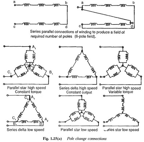
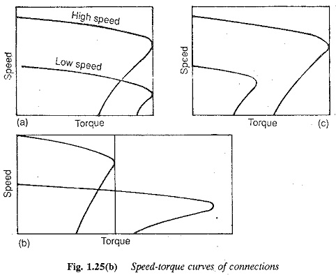
Each phase has a winding split into halves. These are connected either in series or in parallel, to effectively change the number of poles. The possible combinations are shown in Fig. 1.25. Constant power operation is provided by the series-delta connection for high speeds and parallel-star for low speeds. At high speeds, a low torque is developed so that the power is constant. Voltage per half is V/2 in the high speed connection and V/√3 at low speeds.
Series-parallel and series-star connections for high and low speeds respectively
Slip Power Recovery of Induction Motor:
The modification of the speed-torque characteristic using a variable rotor resistance has the major disadvantage of poor efficiency, thus making it uneconomical. Continuous low speed operation is not possible due to overheating of the rotor. These low speeds can be very effectively achieved with reasonable efficiency using slip energy recovery schemes. The slip power which is wasted in the external resistance in the rotor circuit is returned to the mains in these schemes.
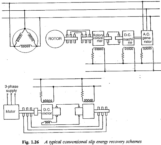
The conventional methods of slip power recovery employ rotating machines, such as rotary converters, alternators, dc machines, etc. in the rotor circuit to convert the power at slip frequency to power at line frequency. Some typical conventional schemes, known as Scherbius and Kramer controls, are shown in Fig. 1.26.
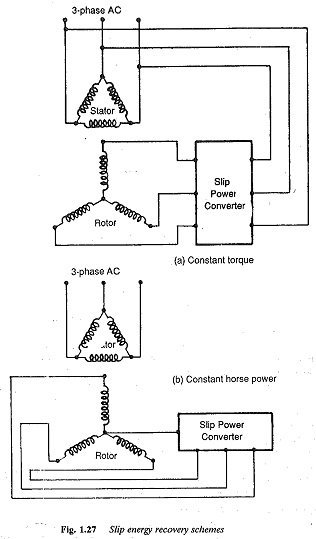
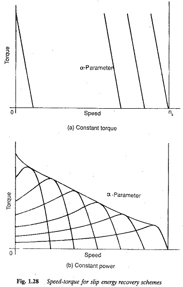
When these methods are employed, the motor /nay be operated to drive both constant torque and constant power loads. These are illustrated in Fig. 1.27(a) and (b), in principle. In Fig. 1.27(a) the rotor power at slip frequency is converted to line frequency by means of a slip converter. If the slip power converter allows power flow in both directions, the motor may be operated both at sub and super synchronous speeds. This scheme is used to drive constant torque loads. In sub synchronous operation the slip power is converted to line frequency and fed to the mains. In supersynchronous operation the power at line frequency is converted to slip power and fed to the motor. One significant feature of this modification is that the developed torque is proportional to rotor current under the assumption of constant flux in the motor. The speed torque curves for this scheme are depicted in Fig. 1.28(a). The desired modification of the torque speed curves shown in Fig. 1.28(a) is achieved by controlling the slip power converter to match the motor voltage at a given slip. The control of the converter is represented by the parameter a. Increase in a increases the voltage on the rotor side of the slip power converter causing a speed drop. a may he fixed for no-load conditions, fixed at no-load value the motor has a drooping speed-torque characteristic. For example a can be the firing angle of the line-side converter in the case of static slip power schemes.
The scheme shown in Fig. 1.27(b) uses the slip power to drive an auxiliary machine. In this case the slip power converter is coupled to the rotor of the induction motor and gets power from it. Here too both sub and super synchronous speeds are possible. In subsynchronous operation the auxiliary machine converts slip power to mechanical power. In supersynchronous operation the additional power is fed to the rotor windings through the slip converter from the auxiliary machine. The connection maintains constant power. The Torque Speed Characteristics of Induction Motor are shown in Fig. 1.28(b). Here also a is a parameter of the slip converter chosen in a manner as to cause the speed control as described above, when varied in a given manner. The slip power is handled by the main motor shaft. The torque decreases with an increase in speed.
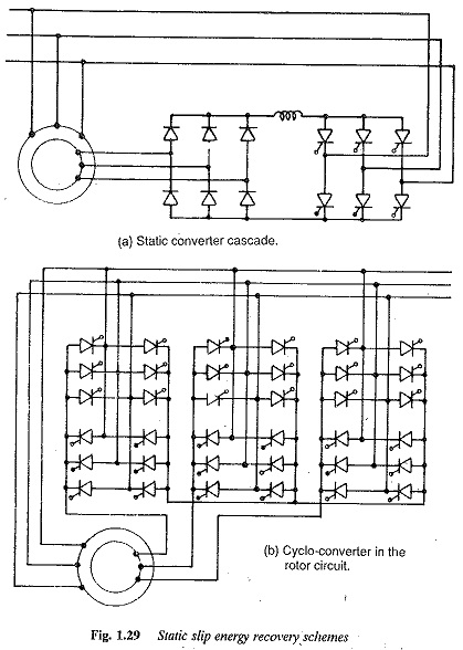
With the availability of thyristor power converters static converter (rectifier-inverter) cascades are being used in the rotor circuits of induction motors to get the abovementioned modifications to the speed-torque characteristic. The schemes are depicted in Fig. 1.29(a). The slip power is rectified and fed to the line commutated converter which feeds the power to the mains. The speed-torque curves obtained by the variation of firing angle of the inverter are shown in Fig. 1.29(6). A cycloconverter may also be used in the rotor circuit.
Injection of Voltage into the Rotor Circuit:
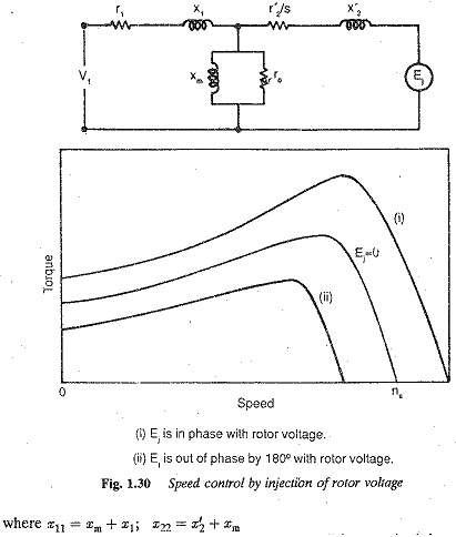
The torque-speed characteristic of an induction motor can be modified by injecting a voltage into the rotor circuit (wound rotor) of an induction motor. The voltage injected must be at slip frequency. If the voltage injected opposes the rotor voltage, the effective rotor current decreases, which instantly affects the torque. The reduced torque cannot drive the load. The rotor speed decreases to a value which ensures sufficient induced rotor voltage and hence rotor current to drive the load. If, on the other hand, the injected voltage aids the rotor voltage, it results in an increased rotor current. The increased torque developed accelerates the rotor to a speed at which sufficient rotor current flows to drive the load. The speed torque curves for the two cases are shown in Fig. 1.30. For comparison, the torque-speed curve of a short circuited rotor with zero injected voltage is also shown. From the figures it can be inferred that it is possible to change the torque capability of the motor by changing the injected voltage. When the injected voltage opposes the rotor current torque capability decreases, whereas it increases when the injected voltage aids the rotor voltage.
Variation of Supply Frequency:
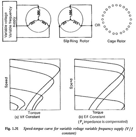
The speed of a synchronously rotating magnetic field is a function of supply frequency. Therefore, by varying the supply frequency the synchronous speed and hence the rotor speed can be varied. To avoid saturation due to an increase in the flux at low frequencies, the applied voltage to the motor is also varied so that the flux remains constant at its rated value at all frequencies. To achieve this a simple method is to vary both voltage and frequency so that V/f is constant. The torque-speed curves with constant V/f are depicted in Fig. 1.31.
There is a depletion of torque at low frequencies. The motor has reduced torque capability and overload capacity. This is because of the dominant effect of stator resistance at low frequencies.
The resistance drop become appreciable as compared to the applied voltage. This causes a depletion of flux, whose constancy cannot be maintained at low frequencies. The torque developed with V/f constant is
To have the same torque and overload capacity at all frequencies it is necessary to compensate for the stator (resistance) drop in order to keep E/f constant. V/f is no longer constant since it increases as the frequency decreases. The torque developed in this case is given by
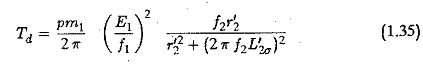
where
L′2σ is rotor leakage inductance.
The torque-speed curves for constant E/f are shown in Fig. 1.31(b).
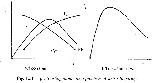
With V/f (constant) control the starting torque increases with a decrease in the frequency, up to a certain value. Below this value of frequency the starting torque decreases. This effect is considered similar to that achieved by changing rotor leakage reactance. As the frequency decreases, the rotor leakage reactance. As the frequency decreases, the rotor leakage reactance decreases. Effectively, an increase in the rotor, resistance relative to leakage reactance takes place. Therefore, the starting torque increases up to a certain frequency, where the rotor leakage reactance equals the rotor resistance.
If the frequency is decreased further the starting torque decreases. The variation of starting torque with frequency is shown in Fig. 1.31(c). However, with constant E/f control the starting torque increases as the frequency decreases up to a value decided by the parameters. If the frequency is further decreased the starting torque decreases. The acceleration may be achieved at constant torque and armature current by varying the stator frequency from a low value keeping E/f constant.
Torque Speed Characteristics of Induction Motor are obtained by increasing the supply frequency beyond the rated value. The flux in the motor decreases, since the voltage cannot be increased beyond the rated value. The motor is said to be operating in the flux weakening mode.
The torque-speed curves run parallel to each other at all frequencies, They extend to the second quadrant, showing that regeneration is possible.
The starting of the motor can be easily accomplished using a variable voltage, variable frequency supply. This decreases the starting current, giving a reasonably good accelerating torque at a good power factor even with low resistance cage motors.
Speed Control of Induction Motor:
A three-phase induction motor is essentially a constant speed motor. It is not possible to achieve smooth speed control of the motor over a wide range, when supplied from a conventional three-phase constant voltage, constant frequency supply. Thyristor power converters have made variable frequency and variable voltage supplies possible. These are employed to get a smooth speed control of induction motors over a wide range.
The methods of modification of Torque Speed Characteristics of Induction Motor discussed are more or less the methods of speed control also. Thyristor power converters are being employed widely in adopting the methods of speed control, e.g. a chopper to control the rotor resistance, ac voltage controller to vary supply voltage, static converter cascades for slip energy recovery, etc.