Power Angle Equation of Synchronous Machine:
Power Angle Equation of Synchronous Machine – In solving the swing equation (Eq. (12.10)), certain simplifying assumptions are usually made. These are:
- Mechanical power input to the machine (Pm) remains constant during the period of electromechanical transient of interest. In other words, it means that the effect of the turbine governing loop is ignored being much slower than the speed of the transient. This assumption leads to pessimistic result—governing loop helps to stabilize the system.
- Rotor speed changes are insignificant—these have already been ignored in formulating the swing equation.
- Effect of voltage regulating loop during the transient is ignored, as a consequence the generated machine emf remains constant. This assumption also leads to pessimistic results—voltage regulator helps to stabilize the system.
Before the swing equation can be solved, it is necessary to determine the dependence of the electrical power output (Pe) upon the rotor angle.
Simplified Machine Model:
For a nonsalient pole machine, the per phase induced emf-terminal voltage equation under steady conditions is
![]()
where
![]()
and usual symbols are used.
Under transient condition
![]()
but

Equation (12.19) during the transient modifies to
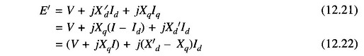
The phasor diagram corresponding to Eqs. (12.21) and (12.22) is drawn in Fig. 12.2.
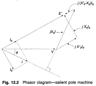
Since under transient condition, X′d < Xd but Xq remains almost unaffected, it is fairly valid to assume that
![]()
Equation (12.22) now becomes
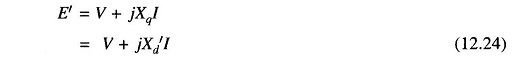
The Power Angle Equation of Synchronous Machine model corresponding to Eq. (12.24) is drawn in Fig. 12.3 which also applies to a cylindrical rotor machine where X′d = X′q = X′s(transient synchronous reactance)
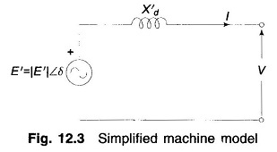
The simplified Power Angle Equation of Synchronous Machine of Fig. 12.3 will be used in all stability studies.
Power Angle Curve of Synchronous Machine:
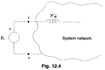
For the purposes of stability studies |E′|, transient emf of generator motor, remains constant or is the independent variable determined by the voltage regulating loop but V, the generator determined terminal voltage is a dependent variable. Therefore, the nodes (buses) of the stability study network pertain to the emf terminal in the machine model as shown in Fig. 12.4, while the machine reactance (X′d) is absorbed in the system network as different from a load flow study. Further, the loads (other than large synchronous motors) will be replaced by equivalent static admittances (connected in shunt between transmission network buses and the reference bus). This is so because load voltages vary during a stability study (in a load flow study, these remain constant within a narrow band).
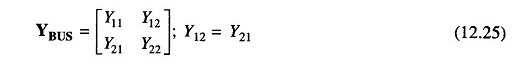
For the 2-bus system of Fig. 12.5
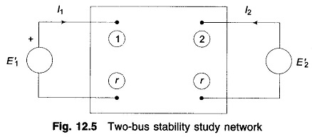
Complex power into bus is given by
![]()
At bus 1
![]()
But
Since in solution of the swing equation only real power is involved, we have from Eq. (12.26)
![]()
A similar equation will hold at bus 2.
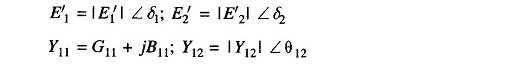
Let

and
![]()
Then Eq. (12.27) can be written as
![]()
For a purely reactive network
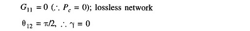
Hence
![]()
where
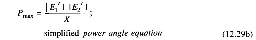
where
- X = transfer reactance between nodes (i.e., between E′1 and E′2)
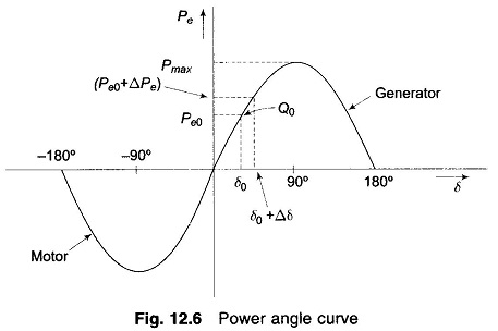
The graphical plot of power angle equation (Eq.(12.29)) is shown in Fig. 12.6.
The swing equation (Eq. (12.10)) can now be written as
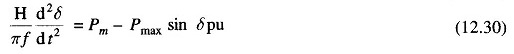
which, as already stated, is a non-linear second-order differential equation with no damping.