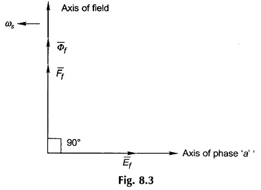
Armature Reaction in Synchronous Motor:
The Simple circuit model of the synchronous machine was obtained in Sec. 8.3 by making the assumption that the magnetic circuit of the machine is linear. However, it is known that, under normal operating conditions, the machine operates in a somewhat saturated region. In order to take account of magnetic saturation a procedure for heuristic adjustment of synchronous reactance was suggested so that the simple circuit model could still be used with the reactance parameter Xs (adjusted). While this does give more accurate results of Armature Reaction in Synchronous Motor for many practical purposes compared to the use of Xs (unsaturated), it still does not fully account for magnetic saturation.
For taking saturation into account, superposition cannot be applied and, therefore, mmf phasor equation,
 must be used from Fig. 8.5 (b).
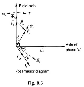
The induced emf’s Ef and Er corresponding to Ff and Fr can be found from the OCC (which takes magnetic saturation into account). The problem, however, is to determine Far for a given armature current Ia, i.e. the Armature Reaction in Synchronous Motor is constant
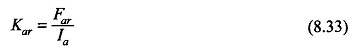
This proportionality constant must be found experimentally for a given machine.
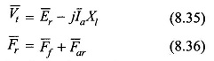
Knowing the magnetization characteristic of the Armature Reaction in Synchronous Motor and the proportionality constant Kar, the phasor diagram of Fig. 8.5(b) can be constructed for given operating conditions (say, for generating mode) wherein no approximation of neglecting the non linearity need be made. The next step then is to find the terminal voltage of the machine which immediately follows from the phasor equation
![]()
The armature resistance, Ra, can be easily measured under dc conditions and duly corrected to its ac value and operating temperature; it can even be altogether neglected without any significant loss of accuracy of analysis since its value is only about 0.01 pu as stated already. However, Xl, the leakage reactance of the machine must be determined. This can be calculated from the design parameters of the machine (provided these are known) but only to a low degree of accuracy. Therefore, it is necessary to obtain its actual value by experimental methods.
Accurate analysis of the Armature Reaction in Synchronous Motor performance can be carried out under any operating conditions provided Kar (Eq. (8.33)) and Xl, the leakage reactance are known. Because of the nonlinearity of iron, there are a variety of experimental methods of determining these quantities to high but varying degrees of accuracy. One of the well known methods called the Potier Method is described here.
Potier Triangle Method:
In the Potier method, tests are conducted to determine the following two characteristics with the machines running at synchronous speed.
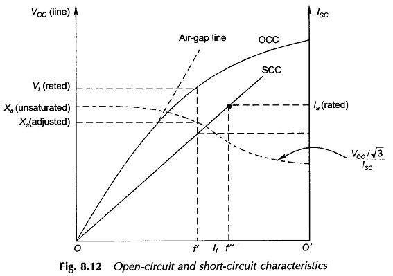
1. Open-circuit characteristic (OCC) as described already, with reference to Fig. 8.12. This is redrawn in Fig. 8.19.
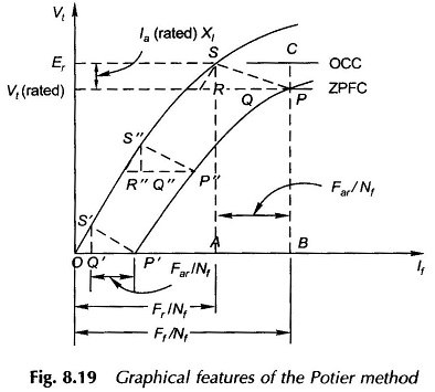
2. Zero power factor (lagging) characteristic (ZPFC). This is conducted by loading the machine as a generator with pure inductive load (balanced 3-phase) which is adjusted to draw rated current from the machine while the field current is adjusted to give various values of terminal voltage.
Figure 8.19 also shows the ZPFC. However, there is no need for conducting this test fully to determine the ZPFC. All one needs is two points on this characteristic—P corresponding to a field current which gives the rated terminal voltage while the ZPF load is adjusted to draw rated current, and the point P’ which corresponds to the short-circuit conditions on the machine (Vt = 0) with the field current adjusted to give rated armature current. Since the armature resistance is of negligible order, the short-circuit current lags behind the resultant induced emf Er by almost 90°, Vt being equal to zero. Therefore, P’ constitutes a point on the ZPFC. It will soon be shown that the complete ZPFC, if required, can be constructed from the knowledge of the points P and P’.
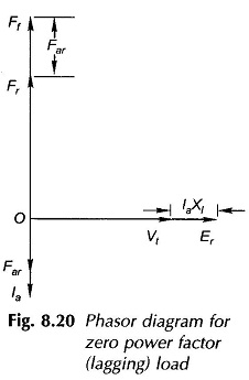
Figure 8.20 gives the phasor diagram under conditions of zero power factor (lagging) load with the armature resistance neglected. It is seen from this figure that the mmf and voltage phasor equations
reduce to simple algebraic equations
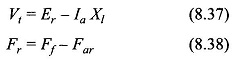
The algebraic Eqs (8.37) and (8.38) can now be translated onto the OCC and ZPFC of Fig. 8.19. Further, in the test data the horizontal axis of Fig. 8.19 being the field current If, Eq. (8.38) must be converted into its equivalent field current form by dividing throughout by Nf, the effective number of turns/pole on the rotor field. It then modifies to
Point P on the ZPFC corresponds to terminal voltage Vt (rated) and a field current of OB = Ff/Nf. Corresponding to point P on the ZPFC, there will be a point S on the OCC which pertains to the emf Er and the resultant excitation OA = Fr/Nf (=Ff/Nf – Far/Nf).
From Fig. 8.19 and Eqs (8.37) and (8.39) it easily follows that
- SQ, the vertical distance between points P and S is nothing but the leakage reactance drop Ia (rated) Xl.
- QP, the horizontal distance between points P and S, is in fact Far/Nf.
It is observed here that while point P is known from the ZPF test, the corresponding point S on the OCC is not yet known because so far the numerical values of Ia (rated) Xl and Far/Nf are not known.
By constructing triangles parallel to SQP, points can be found on the ZPFC corresponding to the points on the OCC, e.g. P” corresponds to S”, and thereby construct the complete ZPFC, if desired. In the reverse process, corresponding to P’, the short-circuit point S’ can be located on the OCC by drawing S’P’ parallel to SP. Obviously
![]()
Since the initial part of the OCC is almost linear, OS’ is a straight line. Therefore going back to point P and by taking horizontal distance RP = OP’ and drawing RS parallel to OS’, the desired point S can be located on the OCC corresponding to the known point P on the ZPFC.
Once point S on the OCC has been located, the following can be measured to scale:![]()
from which Xl and Far can be calculated. Since this Far corresponds to Ia (rated), the armature mmf proportionality constant can be found as
![]()
With the knowledge of Xl and K′ar for the stator windings, the complete phasor diagram of the machine can be constructed corresponding to any operating conditions, generating or motoring.
It must be observed here that the Potier method though elegant is not exact because of the following explicit and implicit assumptions made therein:
- In arriving at the algebraic Eqs. (8.37) and (8.38)/(8.39), the armature resistance has been neglected. This being a very valid assumption, introduces no error of any significance.
- If inductors are used for conducting the ZPF test, the power factor is somewhat different from zero.
- It has been assumed that in Fig. 8.19, S’Q’ = SQ = Ia (rated) Xl which means that in the ZPF test corresponding to point P and the short-circuit test corresponding to point P’, the leakage reactance of the machine is assumed to remain unchanged. This is not altogether correct because the machine excitation under short-circuit conditions is OP’ while it is OA for point P (this point on the ZPFC corresponds to rated terminal voltage and rated armature current). Since OA >> OQ’, point P corresponds to saturated conditions on the Armature Reaction in Synchronous Motor with a larger leakage flux and hence a larger value of leakage reactance contrary to the assumption made.