Kaplan Turbine Working Principle
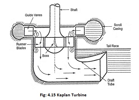
Kaplan Turbine Working Principle: Kaplan Turbine Working Principle - The water from the scroll casing flows over the guide vanes. It is deflected through an angle of 90° in between guide vanes and runner. Then…
Kalman Filtering Approach: The time series approach has been widely employed in dealing with the load forecasting problem in view of the relative simplicity of the model forms. However, this method tends to ignore the…
Junction Field Effect Transistor Theory: n-Channel JFET - The operating principle of an n-channel Junction Field Effect Transistor Theory (JFET) is illustrated by the block representation in Fig. 9-1(a). A piece of n-type semiconductor material,…
Junction Field Effect Transistor (JFET) - Construction, Symbols and Operation: Depending upon the majority charge carriers, Junction Field Effect Transistor (JFET) have been classified into two types, namely (i) N-channel JFETs with electrons as the…
JFET Temperature Effects: The JFET, like other solid state devices, is subject to the JFET Temperature Effects. However, it is possible to bias the JFET such that it will exhibit a zero temperature coefficient i.e.…
JFET Differential Amplifier - Circuit Diagram and its Workings: Many differential amplifiers are constructed with FETs because of the large impedance they present to the input signals—an exceptionally important property in many applications, including operational…
JFET Characteristics: An n-channel JFET Characteristics block representation is shown in Fig. 9-6. With a drain-source voltage applied as illustrated, ID flows in the direction shown producing voltage drops along the channel. Consider the voltage…
JFET Biasing Circuits: Use of Plus/Minus Supplies - When plus/minus supply voltages are to be used with a JFET Biasing Circuits, the gate terminal is usually grounded via RG, as illustrated in Fig. 10-40(a). In…
JFET Bias Circuit Troubleshooting: Voltage Measurement - JFET Bias Circuit Troubleshooting are similar to those for BJT bias circuits. The major difference is that there is only one junction in the FET (the gate-channel junction)…
JFET Bias Circuit Design: Design Approach - Design of JFET Bias Circuit Design is just as simple as design of BJT bias circuits. One major difference is that FET circuit design normally uses a graphical…