Network Topology:
Basically network analysis is nothing but finding unknown branch currents or voltages across various branches. We can find these unknown parameters by using different network simplification techniques. These network simplifications involves basic Kirchhoff’s laws application, loop analysis, nodal analysis, star-delta (λ – Δ) transformations, source shifting and source transformation. The mesh analysis and the nodal analysis are the most useful techniques for the analysis of a Network Topology. But the disadvantage in these techniques is that the selection of unknown variables is difficult. The number of unknown variables increases as the network becomes complicated. Hence in such cases, the network analysis is made really simpler by using concepts in the network topology.
In a network topology, only geometrical structure of a network is considered. Basically any network is the interconnection of various network elements which are either active or passive. Thus in the network topology only geometrical pattern is considered; and different network elements are not considered.
A linear graph is defined as a collection of various nodes and branches. A node is defined as a common point at which two or more branches meet together. A branch is a line joining two nodes which represents a circuit element.
A graph of any network can be drawn by placing all the nodes which are points of intersection of two or more branches. The network elements are represented by the lines joining nodes. The voltage sources and the current
sources are to be replaced by their respective internal impedances. If internal impedances are not known, replace the above mentioned sources by their ideal internal impedances. The ideal internal impedance of a voltage source is zero; so replace the voltage sources in the network by a short circuit in the graph. The ideal internal impedance of a current source is infinite; so replace the current sources in the network by open circuit in the graph. Then nodes and branches are numbered.
Consider a simple electrical network as shown in the Fig. 5.1 (a).
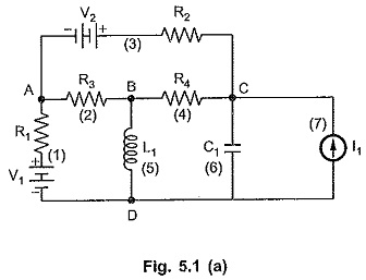
We will first identify the nodes and branches in the network. In the given network, there are 4 nodes and actually 7 branches in which there are network elements. But on the graph we will have only 6 branches because the current source without internal impedance mentioned can be replaced by the open circuit; hence not considered.
As discussed earlier, all the network elements are represented by a short line joining respective nodes.
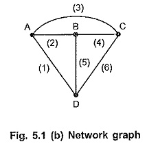
The graph for a given network is as shown in Fig. 5.1 (b). All the branches which are shown in Fig. 5.1 (a), are also shown in the Fig. 5.1 (b) excluding the branch (7).
Particularly the above graph is called an unoriented graph. The graph of a network may be either oriented graph of unoriented graph.
Oriented Graph and Unoriented Graph:
Oriented graph is a graph in which the orientations of the branches are known in the given network and the same are transferred on the graph. The oriented graph is also called directed graph.
Consider following network shown in Fig. 5.2 (a).
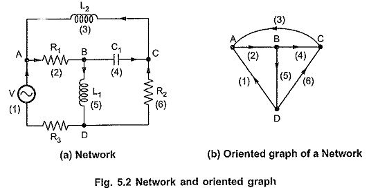
When the directions of the currents are given in the network and the graph is without such orientations, such a graph is called unoriented graph. The graph shown in Fig. 5.2 (b) is unoriented graph.
Planar Graph and Non-planar Graph:
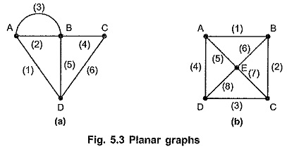
A planar graph is a graph drawn on a two-dimensional plane so that no two branches intersect at a point which is not a node.
The graphs shown in Fig. 5.3 are the planar graphs.
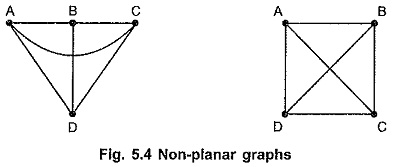
A non planar graph is a graph drawn on a two dimensional plane such that two or more branches intersect at a point other than node on a graph.
The graph shown in the Fig. 5.4 are the non-planar graphs.
Subgraph:
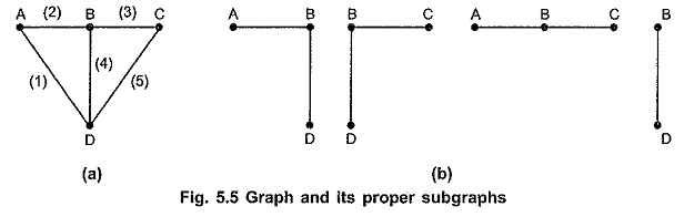
A subgraph is a subset of branches and nodes of a graph. There are two types of a subgraph. If the subgraph contains branches and nodes less in number than those on the graph, then such a subgraph is called proper subgraph.
The graph and its proper subgraphs are as shown in the Fig. 5.5 (a) and (b).
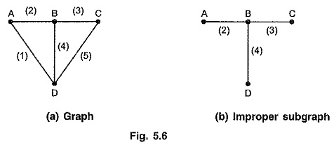
If a subgraph contains all the nodes of a graph and the branches, then a subgraph is called improper subgraph.
A graph and its improper subgraphs are as shown in Fig. 5.6 (a) and (b).
Path:
A path is a improper subgraph such that,
- At the terminating node only one branch is incident.
- At the remaining nodes, two branches are incident.
If a path exists between any pair of nodes, then graph is called connected graph; otherwise it is called disconnected graph.
Rank of a Graph:
If there exists n number of nodes (or the vertices), then the rank R of a graph is given by the relation,
![]()
Tree:
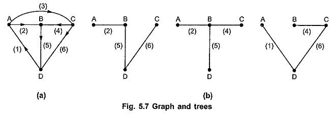
Tree is a set of branches with every node connected to every other node, such that any one of the branches removed changes this property. In other words, we can state that it is a connected subgraph of a connected graph containing all the nodes of the graph not forming any loop. Thus, tree is a set of branches with all nodes not forming any loop or closed path. A graph and some of the possible trees are as shown in Fig. 5.7 (a) and (b).
Properties of Tree:
- Tree contains all nodes on the graph.
- Tree does not contain any closed path.
- In a tree, there exists only one path between any pair of nodes.
- In a tree, minimum end nodes or terminal nodes are two.
- Every connected graph has at least one tree.
- The rank of the tree is same as the rank of graph i.e. (n – 1).
- Tree contain (n – 1) branches if n are the nodes of the tree.
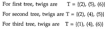
Branch of a Tree (Twig):
A branch of a tree is called twig. If there are n number of nodes on a graph then the tree of a graph contains (n – 1) twigs. Then referring Fig. 5.7 (b), twigs of a tree can be written as follows.
Cotree:
A set of branches forming a complement of tree is called co tree.
The number of branches of a cotree equals b – (n – 1) where b is number of branches of a graph.
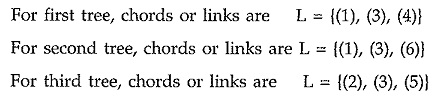
Chord (or Link):
The branches which are not in a tree are called chords or links. Refer Fig. 5.7 (b).
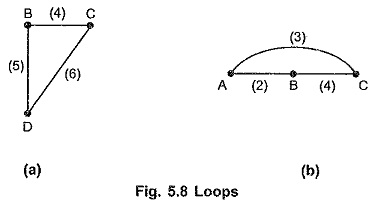
Loop:
In general, a network consists of ‘n’ nodes which are interconnected in some way by ‘b’ branches, then it is possible to traverse adjacent branches starting at any node and return to the original starting node in different ways. Such a closed path formed by the network branches is called as loop.
Loop is a connected subgraph of a connected graph such that at each node there are two branches incident. If the two terminals are made to coincide, it will generate a loop or circuit. The following Fig. 5.8 shows different loops.
Properties of Loops:
A loop of a graph has following properties.
- There are exactly two paths between any pair of nodes in the circuit.
- There exists at least two branches in loop.
- The maximum possible branches in a loop are equal to number of nodes.