Multi Channel Data Acquisition System:
The Multi Channel Data Acquisition System can be time shared by two or more input sources. Depending on the desired properties of the multiplexed system, a number of techniques are employed for such time shared measurements.
Multi-Channel Analog Multiplexed System:
The multi-channel DAS has a single A/D converter preceded by a multiplexer, as shown in Fig. 17.5.
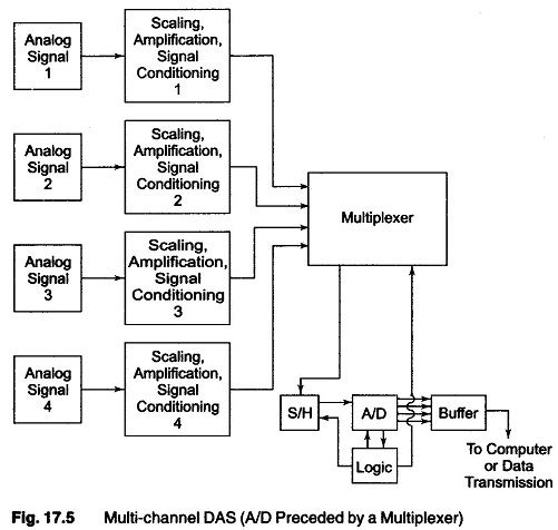
The individual analog signals are applied directly or after amplification and/or signal conditioning, whenever necessary, to the multiplexer. These are further converted to digital signals by the use of A/D converters, sequentially.
For the most efficient utilisation of time, the multiplexer is made to seek the next channel to be converted while the previous data stored in the sample/hold is converted to digital form.
When the conversion is complete, the status line from the converter causes the sample/hold to return to the sample mode and acquires the signal of the next channel. On completion of acquisition, either immediately or upon command, the S/H is switched to the hold mode, a conversion begins again and the multiplexer selects the next channel. This method is relatively slower than systems where S/H outputs or even A/D converter outputs are multiplexed, but it has the obvious advantage of low cost due to sharing of a majority of sub-systems.
Sufficient accuracy in measurements can be achieved even without the S/H, in cases where signal variations are extremely slow.
Multiplexing the Outputs of Sample/Hold:
When a large number of channels are to be monitored at the same time (synchronously) but at moderate speeds, the technique of multiplexing the outputs of the S/H is particularly attractive.
An individual S/H is assigned to each channel as shown in Fig. 17.6, and they are updated synchronously by a timing circuit.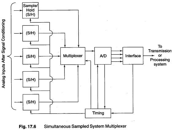
The S/H outputs are connected to an A/D converter through a multiplexer, resulting in a sequential readout of the outputs.
(Applications that might require this approach include wind tunnel measurements, seismographic experimentation, radar and fire control systems. The event to be measured is often a one-shot phenomenon and information is required at a critical point during a one-shot event.)
Multiplexing After A/D Conversion:
It is now economically feasible to employ an A/D converter for each analog input and multiplex the digital outputs.
Since each analog to digital converter (A/D) is assigned to an individual channel, the conversion rate of the A/D need only be as fast as is needed for that channel, compared to the higher rates that would be needed if it were used as in a multi channel analog multiplexed system.
The parallel conversion scheme shown in Fig. 17.7 provides additional advantages in industrial data acquisition systems where many strain gauges, thermocouples and LVDTs are distributed over large plant areas. Since the analog signals are digitised at the source, the digital transmission of the data to the data centre (from where it can go on to a communication channel) can provide enhanced immunity against line frequency and other ground loop interferences. The data converted to digital form is used to perform logic operations and decisions. Based on the relative speed at which changes occur in the data, the scanning rate can be increased or decreased.
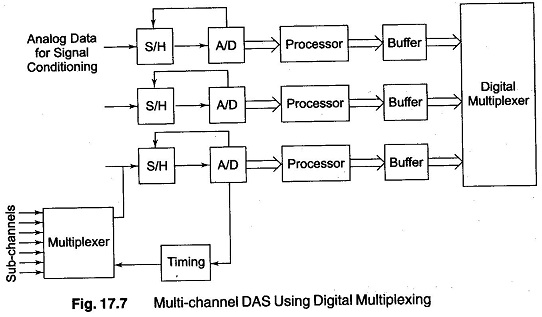
Alternatively, input channels having slowly varying data can be pre-multiplexed in any of the forms suggested earlier, so that a set of sequentially multiplexed sub channels can then replace one channel of the main digital multiplexed system, as indicated in Fig. 17.7.
Multiplexing Low Level Data:
A low level data multiplexing system, as shown in Fig. 17.8, enables the use of a single high quality data amplifier for handling multichannel low level inputs.
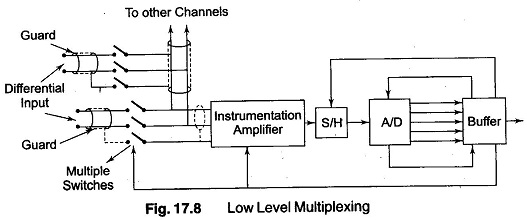
Individual amplifiers are used for each low level signal. Low level multiplexing can be attractive when a large number of channels (25), all having low level outputs, need to be used at moderate speeds. The use of individual channels is possible because of the availability of high quality amplifiers at moderate cost. (A typical application is a 200 channel stress measurement system in a transmission tower set up.)
Several factors have to be considered to accomplish low level multiplexing successfully. Guarding may have to be employed for every channel, and each individual guard may have to be switched, so that the appropriate guard is driven by the common mode pertaining to that channel.
Problems of pickup gets more complicated and have to be taken care of, to preempt the possibility of signal-to-signal, and even common mode-to differential mode signal cross-talk.
Capacitance balance may need to be carried out. When the number of channels to be multiplexed increases, the problems of stray capacitances and capacitive balance are worsened.
In the specific case of a 48 channel system, the input channels are subdivided into groups of eight channels in the first tier. Each of these six subgroups are in turn multiplexed by a six channel multiplexer on the second tier. The main advantage of using this is the reduction of capacitance effects.