LC Immittance Function:
The LC Immittance Function can be LC impedance functions denoted as ZLC(s) or LC admittance functions denoted as YLC(s).
A LC network does not contain power dissipative components i.e. resistances and only consists of reactive elements L and C components. Hence such network is also called a reactance network or lossless network.
Consider a driving point impedance function of LC one port network represented as the ratio of two polynomials in s.
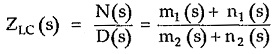
Where m1, n1 are even and odd parts of N(s) while m2, n2 are the even and odd parts of D(s) respectively.
For a purely reactive element jωL or 1/jωC, the real part is zero.
![]()
We have seen that the real part of F(jω) is its even part given by,
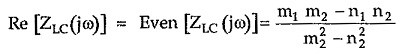
But real part must be zero for LC network.
![]()
Thus to satisfy this equation we must have,
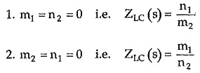
So it can be concluded that the driving point impedance function of LC network is the ratio of odd to even polynomial or even to odd polynomial. This is a very important property of LC network.
For example,
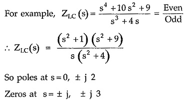
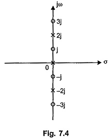
So poles at s = 0, ± j 2
Zeros at s = ± j, ± j 3
The pole zero plot is shown in the Fig. 7.4.
From this impedance function of LC network, let us list the various other properties of LC networks.
Properties of LC Immittance Function:
Referring to the pole zero plot shown in the Fig. 7.4, the properties of ZLC(s) and YLC(s) functions can be stated as,
- The LC Immittance Function is always a ratio of odd to even or even to odd polynomials.
- The poles and zeros are simple. There are no multiple poles or zeros either at origin or infinity or at any point.
- The poles and zeros are located on the jω axis only.
- The poles and zeros interlace (alternate) each other on the jω axis. There are no consecutive poles or zeros on the jω axis.
- The imaginary poles and zeros occur in the form of complex conjugate pairs.
- The highest powers of numerator and denominator must differ by unity.
- The lowest powers of numerator and denominator must differ by unity.
- There must be either a pole or zero at the origin and infinity. As the function is the ratio of even to odd polynomials, if the highest power of numerator is 2m then of denominator is 2m —1 which gives pole at ∞ or it can be 2m +1 which gives zero at ∞. And as lowest powers also differ by unity, there is pole or zero at the origin.
- Residues at the imaginary axis poles are real and positive.
- The number of elements required in any of the four forms of realization is equal to the highest power of s in the LC Immittance Function as a whole.
- The slope of the graph of reactance against frequency is always positive.
We know that there is either pole or zero at the origin.
Consider
So there is pole at the origin. Let us obtain the graph of X(ω). At the starting pole at s= 0 i.e. ω = 0 the X(ω) is infinity. As ω increases, X(ω) also increases and at next critical frequency ω = ω2 where there is a zero, X(ω) becomes zero. As ω further increases from ω = ω2, X(ω) increases and becomes infinity at ω = ω3 where there is a pole. At this frequency, X(ω) suddenly changes the sign and goes from + ∞ to — ∞, such that as we pass through ω = ω3, slope of the graph always remains positive. It becomes zero at ω = ω4 where there is a zero. The nature continues such that the slope d/dω [X(ω)] always positive. The nature is shown in the Fig. 7.5 for the Z(s) considered.
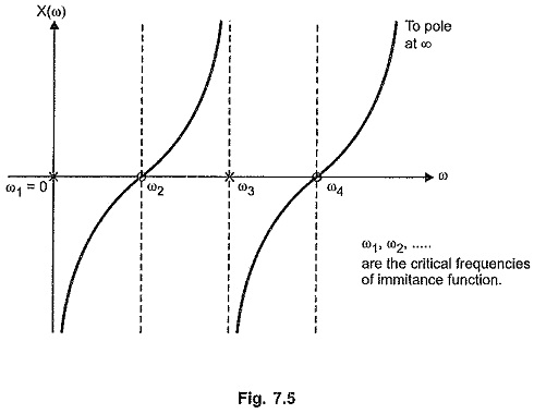
Between ω1 and ω2, nature of X(ω) is capacitive while between ω2 and ω3 it is inductive. At ω3 = 2, it changes from inductive to capacitive suddenly so that slope of the graph remains always positive.
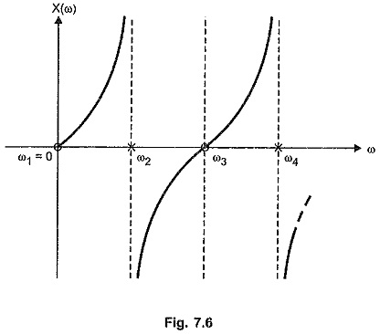
For a zero at the origin, the reactance curve takes the form as shown in the Fig. 7.6.
For a LC function,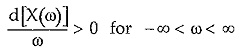
From the nature of the reactance curves shown in the Fig. 7.5 and 7.6 with pole at origin and zero at origin respectively, it can be seen that curve has to change its sign at the poles to maintain the positive slope.
Hence to maintain the positive slope, the poles and zeros must separate each other and in such a way that the poles and the zeros alternate along the real frequency axis. This is called Separation Property or Foster Reactance Theorem for the reactance functions.
Thus if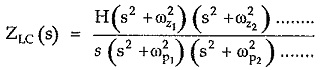
then H is scale factor. Now ωz1 can be zero which gives zero at the origin or has finite existence if there is pole at the origin.
According to the Reactance theorem pole and zero frequencies must satisfy the relation given by,
![]()
Realization of Immitance Function of LC Networks:
The realization of driving point immitance functions of LC networks can be done by any of the four forms discussed earlier. The forms which are used are,
- Foster I form
- Foster II form
- Cauer I form
- Cauer II form