Heterodyne Wave Analyzer:
Wave analyzers are useful for measurement in the audio frequency range only. For measurements in the RF range and above (MHz range), an ordinary wave analyzer cannot be used. Hence, special types of wave analyzers working on the principle of heterodyning (mixing) are used. These wave analyzers are known as Heterodyne Wave Analyzer.
In this wave analyzer, the input signal to be analyzed is heterodyned with the signal from the internal tunable local oscillator in the mixer stage to produce a higher IF frequency.
By tuning the local oscillator frequency, various signal frequency components can be shifted within the pass-band of the IF amplifier. The output of the IF amplifier is rectified and applied to the meter circuit.
An instrument that involves the principle of heterodyning is the Heterodyning tuned voltmeter, shown in Fig. 9.3.
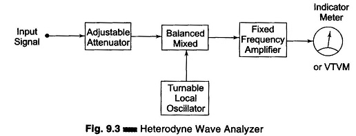
The input signal is heterodyned to the known IF by means of a tunable local oscillator. The amplitude of the unknown component is indicated by the VTVM or output meter. The VTVM is calibrated by means of signals of known amplitude.
The frequency of the component is identified by the local oscillator frequency, i.e. the local oscillator frequency is varied so that all the components can be identified. The local oscillator can also be calibrated using input signals of known frequency. The fixed frequency amplifier is a multistage amplifier which can be designed conveniently because of its frequency characteristics. This analyzer has good frequency resolution and can measure the entire AF frequency range. With the use of a suitable attenuator, a wide range of voltage amplitudes can be covered. Their disadvantage is the occurrence of spurious cross-modulation products, setting a lower limit to the amplitude that can be measured.
Two types of selective amplifiers find use in Heterodyne wave analyzers. The first type employs a crystal filter, typically having a centre frequency of 50 kHz. By employing two crystals in a band-pass arrangement, it is possible to obtain a relatively flat pass-band over a 4 cycle range. Another type uses a resonant circuit in which the effective Q has been made high and is controlled by negative feedback. The resultant signal is passed through a highly selective 3-section quartz crystal filter and its amplitude measured on a Q-meter.
When a knowledge of the individual amplitudes of the component frequency is desired, a heterodyne wave analyzer is used.
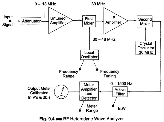
A modified heterodyne wave analyzer is shown in Fig. 9.4. In this analyzer, the attenuator provides the required input signal for heterodyning in the first mixer stage, with the signal from a local oscillator having a frequency of 30 – 48 MHz.
The first mixer stage produces an output which is the difference of the local oscillator frequency and the input signal, to produce an IF signal of 30 MHz. This IF frequency is uniformly amplified by the IF amplifier. This amplified IF signal is fed to the second mixer stage, where it is again heterodyned to produce a difference frequency or IF of zero frequency.
The selected component is then passed to the meter amplifier and detector circuit through an active filter having a controlled band-width. The meter detector output can then be read off on a db – calibrated scale, or may be applied to a secondary device such as a recorder.
This wave analyzer is operated in the RF range of 10 kHz – 18 MHz, with 18 overlapping bands selected by the frequency range control of the local oscillator. The bandwidth, which is controlled by the active filter, can be selected at 200 Hz, 1 kHz and 3 kHz.