Frequency Response for Low Pass Filter and High Pass Filter:
The Fig. 2.71 shows the Frequency Response for Low Pass Filter. A low pass filters has a constant gain from 0 Hz to a high cut-off frequency, fH. Hence, the bandwidth of this filter is also fH. The ideal characteristics is shown in Fig. 2.71 (a).
Low Pass Filter Frequency Response:
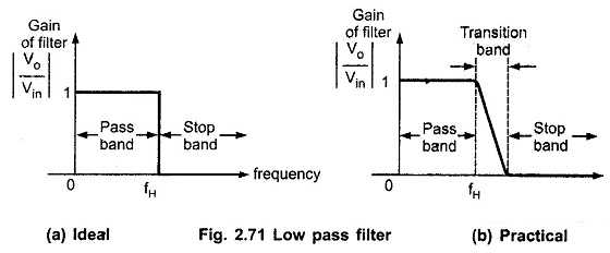
The circuit allows the range of frequencies from 0 to fH. This range is known as the pass band. The range of frequencies beyond fH, is completely attenuated and hence called as stop band.
Practically, the gain of the filters decreases as the frequency increases and at f = fH, the gain is down by 3 dB and after fH, it decreases at a higher rate. After the end of transition band, the gain becomes zero.
Using proper design techniques, precision component values and high speed op-amps, the practical response can be obtained very close to the ideal response.
High Pass Filter Frequency Response:
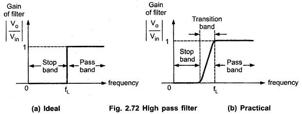
The Fig. 2.72 shows the frequency response of high pass filters. For a high pass filter, fL is the low cut off frequency. The range of frequency 0 < f < fL is the stop band where f is the operating frequency. While the range of frequency f > fL is the passband. The Fig. 2.72 (a) shows the ideal high pass filter characteristics while Fig. 2.72 (b) shows the practical high pass filter characteristics.
The transition band is practically not shown in the characteristics as it is very small. Hence, practically, also range upto fL is called as stop band and f > fL as pass band. The range up to fL is completely attenuated by high pass filters.