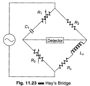
Electronic Instrumentation

Hays Bridge Circuit

Hays Bridge Circuit: Hays Bridge Circuit, shown in Fig. 11.23, differs from Maxwell’s bridge by having a resistance R1 in series with a standard capacitor C1 instead of a parallel. For large phase angles, R1 needs to be low; therefore, this bridge is more convenient for measuring high-Q coils. For Q = 10, the error is […]

Hays Bridge Circuit Read More »

Maxwell Bridge Theory

Maxwell Bridge Theory: Maxwell Bridge theory, shown in Fig. 11.21, measures an unknown inductance in terms of a known capacitor. The use of standard arm offers the advantage of compactness and easy shielding. The capacitor is almost a loss-less component. One arm has a resistance R1 in parallel with C1, and hence it is easier

Maxwell Bridge Theory Read More »

Comparison Bridge

Comparison Bridge: There are two types of Comparison Bridge, Namely Capacitance Comparison Bridge Inductance Comparison Bridge 1. Capacitance Comparison Bridge: Figure 11.18 shows the circuit of a capacitance comparison bridge. The ratio arms R1, R2 are resistive. The known standard capacitor C3 is in series with R3. R3 may also include an added variable resistance

Comparison Bridge Read More »

Bridge Controlled Error Detection

Bridge Controlled Error Detection

Bridge Controlled Error Detection: Bridge Controlled Error Detection – Whenever a bridge is unbalanced, a potential difference exists at its output terminal. The potential difference causes current to flow through the detector (say, a galvanometer) when the bridge is used as part of a measuring instrument. When the bridge is used as an error detector

Bridge Controlled Error Detection Read More »

Wheatstone Bridge Diagram

Wheatstone Bridge Diagram: A Wheatstone Bridge diagram in its simplest form consists of a network of four resistance arms forming a closed circuit, with a dc source of current applied to two opposite junctions and a current detector connected to the other two junctions, as shown in Fig. 11.1. Wheatstone Bridge diagram are extensively used

Wheatstone Bridge Diagram Read More »

pH Measurement Methods

pH Measurement Methods: pH is defined as the negative logarithm of the active hydrogen ion. It is a measure of the acidity or alkalinity of an aqueous solution. The pH scale runs from 0 – 14, with pH 7, the neutral point, being the pH of pure water at 25°C. The lower the pH value,

pH Measurement Methods Read More »

Megger Circuit Diagram

Megger Circuit Diagram: Another common method of measuring resistances above 50 M Ω is the Megger Circuit Diagram (megaohmmeter) shown in Fig. 10.23(a). This instrument is used to measure very high resistances, such as those found in cable insulations, between motor windings, in transformer windings, etc. Construction and Working Principles: Normal (shop) VOMs do not

Megger Circuit Diagram Read More »

Scroll to Top