Oscilloscope Articles:
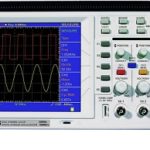
Introduction to Oscilloscopes: The Cathode Ray Oscilloscope is probably the most versatile tool for the development of electronic circuits and systems. The Cathode Ray Oscilloscope allows the amplitude of electrical signals, whether they are voltage, current, or power, … (Read More)
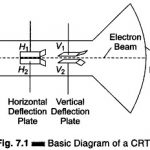
What is Cathode Ray Tube (CRT) of an Oscilloscope? To understand the principle of an Electron Beam Experiment in CRT, let us consider a torch which is focused on a piece … (Read More)
CRT Features: Electrostatic CRTs are available in a number of types and sizes to suit individual requirements. The important features of these tubes are as follows. 1. Size Size refers to the screen diameter. CRTs for oscilloscopes are available in … (Read More)
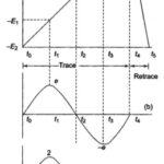
What is the Principle of Sweep Generator?: The amplitude of a voltage may be directly measured on a calibrated viewing screen from the length of the straight line trace it produces. This is entirely satisfactory for … (Read More)
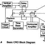
Block Diagram of Oscilloscope: The major Block Diagram of Oscilloscope shown in Fig. 7.4, of a general purpose CRO, is as follows: CRT Vertical amplifier Delay line Time base Horizontal amplifier Trigger circuit Power Supply The function of the various blocks are as follows. 1. CRT This is the cathode ray … (Read More)
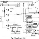
Block Diagram of CRO: The Basic Block Diagram of CRO is shown in Fig.7.5. The ac filament supplies power to the CRT heaters in the Block Diagram of CRO. This also provides as accurate ac calibrating voltage. CRT dc voltage is … (Read More)
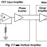
Vertical Amplifier: The sensitivity (gain) and frequency bandwidth (B.W.) response characteristics of the oscilloscopes are mainly determined by the vertical amplifier. Since the gain B.W. product is constant, to obtain a greater sensitivity the B.W. is narrowed, or vice-versa. Some oscilloscopes give … (Read More)
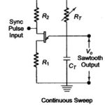
Horizontal Deflection System in CRO: The Horizontal Deflection System in CRO consist of a Time Base Generator and an output amplifier. Sweep or Time Base Generator: A continuous sweep CRO using a UJT as a time base generator is shown in Fig. 7.8. … (Read More)
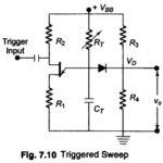
Triggered Sweep CRO: The continuous sweep is of limited use in displaying periodic signals of constant frequency and amplitude. When attempting to display voice or music signals, the pattern falls in and out of sync as the … (Read More)
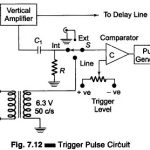
Trigger Pulse Generator Circuit: The Trigger Pulse Generator Circuit is activated by signals of a variety of shapes and amplitudes, which are converted to trigger pulses of uniform amplitude for the precision sweep operation. If the trigger level is set too … (Read More)
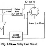
Delay Line in Triggered Sweep Circuit: Figure 7.13 shows a Delay Line in Triggered Sweep Circuit. Figure 7.14 indicates the amplitude of the signal wrt time and the relative position of the sweep generator output signal. The diagram shows that when the … (Read More)
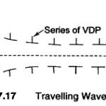
High Frequency CRT or Travelling Wave Type CRT: Figure 7.17 illustrates a High Frequency CRT. In an ordinary CRO, there is only one pair of VDPs. When the signal to be displayed is of a very high frequency CRT, the electron beam … (Read More)
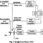
Dual Beam CRO Block Diagram and Working Principle: Figure 7.18 illustrates a block diagram of a Dual Beam CRO. The dual trace oscilloscope has one cathode ray gun, and an electronic switch which switches two signals to a single vertical amplifier. The … (Read More)
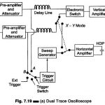
Dual Trace Oscilloscope: Figure 7.19 (a) shows a block diagram of Dual Trace Oscilloscope. This CRO has a single electron gun whose electron beam is split into two by an electronic switch. There is one control for focus and another for intensity. … (Read More)
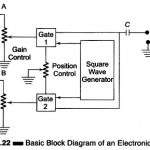
What is Electronic Switch in Oscilloscope? The electronic switch is a device that enables two signals to be displayed simultaneously on the screen by a single gun CRT. The basic block diagram of an Electronic Switch Circuit is shown in Fig. … (Read More)
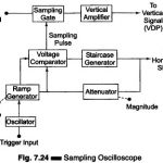
What is Sampling Oscilloscope? An ordinary Sampling Oscilloscope has a B.W. of 10 MHz. The HF performance can be improved by means of sampling the input waveform and reconstructing its shape from the sample, i.e. the signal to be observed is … (Read More)
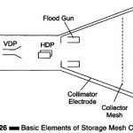
Storage Oscilloscope (For VLF Signal): Storage Oscilloscope – Storage targets can be distinguished from standard phosphor targets by their ability to retain a waveform pattern for a long time, independent of phosphor peristence. Two storage techniques are used in oscilloscope CRTs, … (Read More)
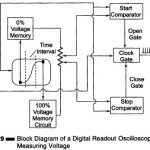
Digital Readout Oscilloscope: The Digital Readout Oscilloscope instrument has a CRT display and a counter display. The diagram shown is of an instrument where the counter measures the time (Fig. 7.29). The input waveform is sampled and the sampling circuit advances the … (Read More)
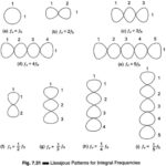
Frequency Measurement by Lissajous Method: The oscilloscope is a sensitive indicator for frequency and phase measurements. This Frequency Measurement by Lissajous Method techniques used are simple and dependable, and measurement may be made at any frequency in the response range of … (Read More)
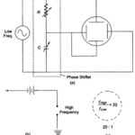
Spot Wheel Method for Frequency Measurement: As the ratio of the two frequencies being compared increases, the Lissajous pattern becomes more complicated and hence more difficult to interpret. In such cases, it is advantageous to use the Spot Wheel Method for … (Read More)
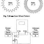
Gear Wheel Method for Frequency Measurement: When a Lissajous figure contains a large number of loops, accurate counting becomes difficult. Figure 7.35 shows a test method that uses a modulated ring pattern in place of the looped figure and permits a … (Read More)
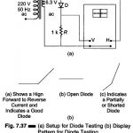
Setup for Diode Testing in Oscilloscope: Diode Testing in Oscilloscope -The voltage-current characteristics curve of a crystal diode may be observed using the circuit given in Fig. 7.37 (a). In this case the internal sweep is not used. Horizontal deflection is obtained … (Read More)
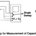
Measure of Capacitance and Inductance in Oscilloscope: Measure of Capacitance and Inductance in Oscilloscope – Capacitance may be measured from a capacitor discharge curve. This requires a dc oscilloscopes with a triggered single sweep that is of the storage type. Figure 7.38 … (Read More)
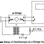
Oscilloscope as a Bridge Null Detector: As a null detector for an ac bridge, the oscilloscope, unlike a meter used for the purpose, gives separate indications for reactive and resistive balances of the bridge. Figure 7.40 shows how an oscilloscope is connected … (Read More)
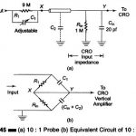
Probes for CRO: Direct Probes (1 : 1): The simplest types of Probes for CRO (one can hardly call it a probe) is the test lead. Test leads are simply convenient lengths of wire for connecting the CRO input to the point … (Read More)
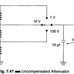
Attenuators: Attenuators are designed to change the magnitude of the input signal seen at the input stage, while presenting a constant impedance on all ranges at the attenuator input. A compensated RC attenuator is required to attenuate all frequencies equally. Without this … (Read More)
Applications of Oscilloscope: The range of applications of oscilloscope varies from basic voltage measurements and waveform observation to highly specialized applications in all areas of science, engineering and technology. Voltage Measurements: The most direct voltage measurement made with the help of an oscilloscope … (Read More)
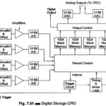
What is Digital Storage Oscilloscope (DSO)? Digital Storage Oscilloscope are available in processing and non-processing types. Processing types include built in computing power, which takes advantage of the fact that all data is already in digital form. The inclusion of interfacing and … (Read More)
Fibre Optic CRT Recording Oscilloscope: Fibre Optic CRT Recording Oscilloscope – The familiar CRT oscilloscope has an extremely HF response, but permanent records, normally photography of the screen, cannot be taken, since they are time limited to one sweep. By combining a … (Read More)
Oscilloscope Operating Precautions: In addition to the general safety precautions, the following specific precautions should be observed when operating any type of oscilloscope. Most of the Oscilloscope Operating Precautions also apply to recorders. Always study the instruction manual of any oscilloscope with … (Read More)
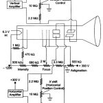
Various CRT Connections and Controls in CRO Panel: Figure 7.16 shows various controls and Typical CRT Connections. The following controls are available on CRO panel. Intensity: It controls the magnitude of emission of the electron, beam, i.e. the electron beam is adjusted … (Read More)
Delayed Sweep Oscilloscope: Many oscilloscopes of laboratory quality include a delayed sweep feature. Delayed Sweep Oscilloscope feature increases the versatility of the instrument by making it possible to magnify a selected portion of an undelayed sweep, measure waveform jitter or rise … (Read More)