Vertical Amplifier:
The sensitivity (gain) and frequency bandwidth (B.W.) response characteristics of the oscilloscope are mainly determined by the vertical amplifier. Since the gain B.W. product is constant, to obtain a greater sensitivity the B.W. is narrowed, or vice-versa.
Some oscilloscopes give two alternatives, switching to a wide bandwidth position, and switching to a high sensitivity position.
Block Diagram of a Vertical Amplifier:
The block diagram of a vertical amplifier is shown in Fig. 7.7.
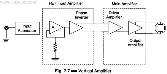
The vertical amplifier consists of several stages, with fixed overall sensitivity or gain expressed in V/divs. The advantage of fixed gain is that the amplifier can be more easily designed to meet the requirements of stability and B.W. The vertical amplifier is kept within its signal handling capability by proper selection of the input attenuator switch. The first element of the pre-amplifier is the input stage, often consisting of a FET source follower whose high input impedance isolates the amplifier from the attenuator.
This FET input stage is followed by a BJT emitter follower, to match the medium impedance of FET output with the low impedance input of the phase inverter.
This phase inverter provides two antiphase output signals which are required to operate the push-pull output amplifier. The push-pull output stage delivers equal signal voltages of opposite polarity to the vertical plates of the CRT.
The advantages of push-pull operation in CRO are similar to those obtained from push-pull operation in other applications; better hum voltage cancellation from the source or power supply (i.e. dc), even harmonic suppression, especially the large 2nd harmonic is cancelled out, and greater power output per tube as a result of even harmonic cancellation. In addition, a number of defocusing and non-linear effects are reduced, because neither plate is at ground potential.