Power Flow Equation of Synchronous Generator:
Power Flow Equation of Synchronous Generator – The flow of active and reactive power in a synchronous link will now be studied. The approach will be analytical and armature resistance will be considered for generality of results. Figure 8.42 shows the schematic diagram of a synchronous generator wherein E̅f leads V̅t by angle δ. The synchronous impedance is
![]()
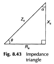
as shown by the impedance triangle wherein
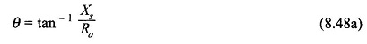
and
![]()
The armature current in Fig. 8.42 can be expressed as
![]()
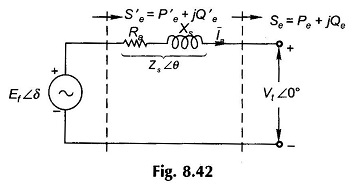
The complex power output is
![]()
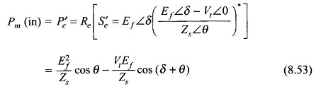
Substituting for Ia from Eq. (8.49) in Eq. (8.50),
![]()
Equating the real and imaginary parts of Eq. (8.51), the following expressions for real and reactive power output are obtained as
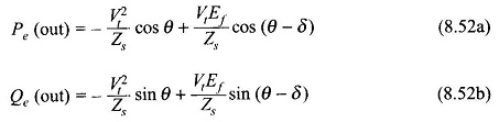
The net mechanical power input to the machine is given by
It is convenient to express the above results in terms of angle α defined in the impedance triangle of Fig. 8.43 (Eq. 8.48b). Equations (8.52a), (8.52b) and (8.53) then modify as below
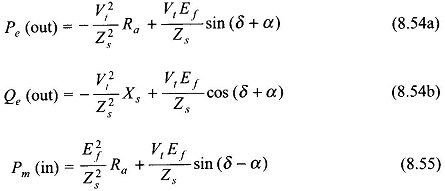
The real electrical power output, Pe, as per Eq. (8.54a) is plotted in Fig. 8.44 from which it is observed that its maximum value is
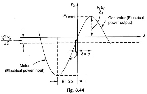
![]()
occurring at δ= θ, which defines the limit of steady-state stability. The machine will fall out of step for angle δ> θ. Of course, θ will be 90° if resistance is negligible in which case the stability limit will be at δ= 90° as already explained
It follows from Eq. (8.55) that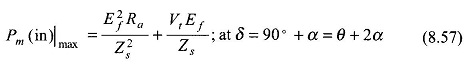
Since the angle δ in Eq. (8.57) is more than θ, the maximum mechanical power input (net) operation for a generator lies in the unstable region.
Equations (8.54a), (8.54b), (8.55) and (8.56) simplify as below when armature resistance is neglected
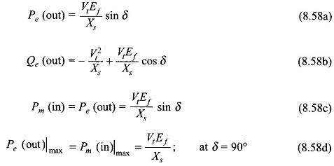
Figure 8.45 shows the operation of the synchronous machine as a motor. Here the angle δ by which Ef lags Vt is defined as positive. Also the direction of power flow is now into the machine while the mechanical power flows out at the machine.
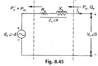
It then follows from Eqs (8.54a), (8.54b) and (8.55) by changing the sign of δ that for motoring operation
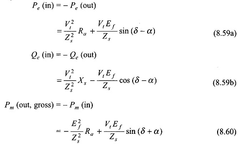
The maximum mechanical power output from Eq. (8.60) is given by
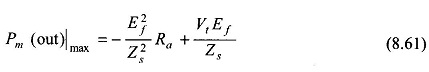
It occurs at δ = θ which defines the limit of steady-state stability. It is easily seen from Eq. (8.59a) that the maximum electrical power input occurs at δ = θ + 2α which lies outside the stability limit. The reader should compare these results Power Flow Equation with that of the generator.
For the case of negligible resistance, the Power Flow Equation of Synchronous Generator is given by
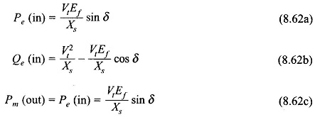
For unity pf operation Qe= 0 in Eq. (8.62b) which occurs when
![]()