Microprocessor Based Ramp Type DVM:
A basic block diagram of a Microprocessor Based Ramp Type DVM and its operating waveform is shown in Fig. 5.17 (a) and (b) respectively. Depending on the command fed to the control input of the multiplexer by the microprocessor, input 1 of the comparator can be consecutively connected to the input 1, 2 or 3 of the multiplexer.
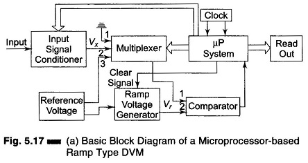
The multiplexer has three inputs — input 1 is connected to ground potential, input 2 is the unknown input, and input 3 is the reference voltage input. The comparator has two inputs — input 1 accepts the output signal from the multiplexer, and input 2 accepts the ramp voltage from the ramp generator.
The microprocessor remains suspended in the resting state until it receives a command to start conversion. During the resting period, it regularly sends reset signals to the ramp generator. Each time the ramp generator is reset, its capacitor discharges. It produces a ramp, i.e. a sawtooth voltage whose duration, Tr and amplitude, Vm remain constant. The time duration between the consecutive pulses is sufficiently large enough for the capacitor to get discharged.
Whenever a conversion command arrives at the microprocessor at a time t1, the multiplexer first connects input 1 of the comparator to its input 1 (i.e. ground potential) and brings the former to ground potential.
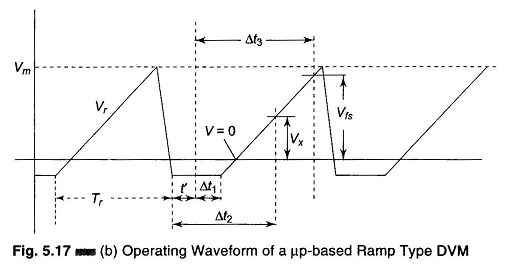
The microprocessor pauses until another sawtooth pulse begins. When input 2 voltage, arriving from the ramp generator becomes equal to equal to input 1 of the comparator, the comparator sends a signal to the microprocessor, that ramp voltage is zero. The microprocessor measures this time interval Δt1 (shown in Fig. 5.17 (b)), by counting the number of clock pulses supplied by the clock generator during this time interval. Let the count during this time be N1, which is then stored by the microprocessor. A command from the microprocessor now causes the comparator input 1 to be connected to input 2 of the multiplexer. This connects the unknown voltage, Vx to the input 1 of the comparator. At an instant, when the ramp voltage equals the unknown voltage, the comparator sends a signal to the microprocessor the measure the time interval Δt2 (Fig. 5.17 (b)). The count N2, during this time interval is also stored.
Now, the next command from the microprocessor causes the comparator input 1 to be connected to the input 3 of the multiplexer, which is the reference voltage (full scale voltage). The value of the reference voltage sets the upper limit of measurement, that is, full scale value. At the instant, when the ramp voltage equals the reference voltage, a pulse is sent to the microprocessor from the comparator output to measure this time interval, Δt3 (Fig. 5.17 (b)). The count, N3 during this time interval is also stored.
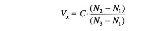
The microprocessor then computes the unknown voltage Vx by the equation
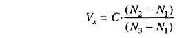
where C is the coefficient dependent on the characteristics of the instrument and the units selected to express the result.
In this method of measurement, the zero drift has practically no effect on the result, because of the variation of slope of the ramp.
Hence from the Fig. 5.17 (b),
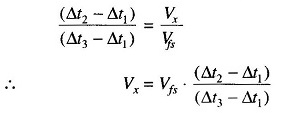
Since the clock pulse repetition frequency fc and full scale voltage Vfs are maintained at a very high level of stability and clock pulses allowed to fall within all the time intervals come from a common source, the above equation may be rewritten as
where N1, N2, N3 are the counts representing respectively, the zero drift, the unknown voltage, and the full scale voltage.
Advantages of Microprocessor Based Ramp Type DVM:
- Its scale size remains constant due to zero drift correction and maximum
- The accuracy of the instrument is not affected by the time and temperature instabilities of the circuit element values.
- There is a good repeatability in switching instants in the presence of noise and interference. This is because the ramp approaches the point at which the comparator operates always the same side and always the same rate.
Disadvantages of Microprocessor Based Ramp Type DVM:
- Noise and interference cannot be suppressed.