Diode Series Clipper Circuit:
The function of a Diode Series Clipper Circuit (or limiter) is to clip off an unwanted portion of a waveform. This is sometimes necessary to protect a device or circuit that might be destroyed by a large amplitude (negative or positive) signal.
A half-wave rectifier can be described as a clipper, because it passes only the positive for negative) half-cycle of an alternating waveform and clips off the other half-cycle. In fact, a diode series clipper is simply a half-wave rectifier circuit.
Figure 3-25(a) shows a negative series clipper circuit with a square wave input symmetrical above and below ground level. While the input is positive, Di is forward biased and the positive half-cycle is passed to the output.
![]()
During the negative half-cycle of the input, the diode is reverse biased. Consequently, the output remains at zero and the negative half-cycle is effectively clipped off.
The zero level output from a series clipper circuit is not exactly zero. The reverse saturation current (IR) of the diode produces a voltage drop across resistor R1,![]()
This is almost always so small that it can be neglected.
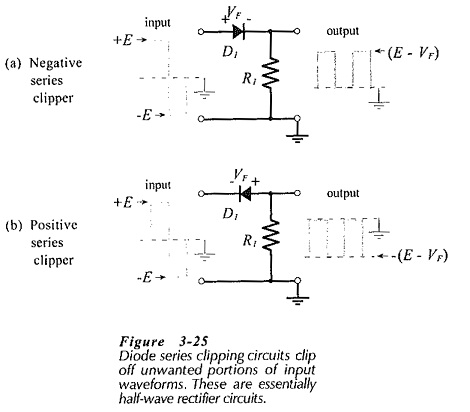
If the diode in Fig. 3-25(a) is reconnected with reversed polarity, as shown in Fig. 3-25(b), the positive half-cycles are clipped off, and the circuit becomes a positive series clipper. The input wave forms to a clipper may be square, or sinusoidal, or any other shape.
The output terminals of series clippers are usually connected to circuits that have a high input resistance, so (current-limiting) resistor R1 is selected to pass an acceptable minimum current through the diode. This current must be sufficient to operated the diode beyond the knee of its forward characteristic. Typically, a current of 1 mA is appropriate. The resistor value is calculated from the output voltage and the selected current level. The remaining part of the design process is specifying the diode.
Current Level Selection:
In most electronic circuits it is best to select the smallest possible level of current. One reason for this is to keep the total supply current to a minimum. High supply currents require larger, more expensive, power supplies than low current levels. Where a battery supply is used, batteries last longer with low supply current levels. Another reason to keep circuit current levels low whenever possible, is to minimize component power dissipation. Low power dissipation allows the smallest components to be used, and avoids circuit heating problems.
Series Noise Clipper:
Digital signal wave forms sometimes have unwanted lower-level noise voltages. The noise can be removed by a series noise clipping circuit, which simply consists of two inverse-parallel connected diodes, as illustrated in Fig. 3-27. When the noise amplitude is much smaller than the diode forward voltage drop (VF), and the signal amplitude is larger than VF, the signals are passed and the noise is blocked. The signal peak output voltage is (E -VF).
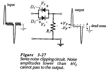
A dead zone of ±VF exists around ground level in the output waveform, indicating that inputs must exceed ±VF to pass to the output. For noise voltage amplitudes that approach ±VF, two diodes may be connected in series to give a larger dead zone.