Three Phase Cycloconverter – Types, Working and Applications:
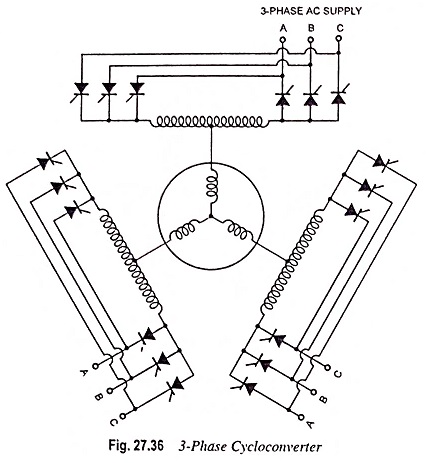
A cycloconverter converts ac at one frequency to an ac of another frequency. Cycloconverters can be classified as single-phase to single-phase, three-phase to single-phase and three-phase to 3-phase devices. They can also be classed as step-up and step-down cycloconverters. A step-up cycloconverter provides an output whose frequency is higher than that of input while a step-down cycloconverter provides an output of frequency lower than that of input. Step-down cycloconverter uses line or natural commutation. Cycloconverters were developed initially for electric traction systems operating at 25 Hz and 16 2/3 Hz. In their early stages of use, the cycloconverters used mercury-arc rectifiers. With the development of thyristors the applications of cycloconverters have increased. The basic power circuit scheme of a three phase cycloconverter is shown in Fig. 27.36.
Independent control of output frequency and voltage is obtained with only one parameter variation, i.e., viz., by variation of the firing points of the controlled rectifiers. The frequency of the output voltage is controlled by the rate at which the firing points are varied about the quiescent point and the output voltage is controlled by the maximum excursion of the firing points from the quiescent point. The three phase cycloconverter, with its associated firing circuit, produces an output voltage that is replica of the reference voltage.
Operation:
The operation of three phase cycloconverter is characterized by several features. They are, generally, employed as step-down frequency converters. There is no fixed minimum ratio of input to output frequency; however, the output frequency is restricted typically to one-third or one-half of the input or line frequency. Below these ratios, the efficiencies of both the cycloconverters and motors supplied by them start falling significantly.
Reversibility is another feature of cycloconverter drive systems. A cycloconverter fed ac motor drive will respond to a change in polarity of the input signals by changing the direction of rotation of the motor without the use of contactors to reverse phase sequence.
The ability of cycloconverter to handle power flow in either direction is another important feature. This, together with the above mentioned reversibility feature, provides an induction motor drive capable of operating in any of the four quadrants of the motor’s speed-torque curve.
While the cycloconverter has many attractive features from a theoretical point of view, there are several limitations because of which they have not gained popularity. It needs more power semiconductors than an inverter. For example, the three phase cycloconverter needs 18 thyristors, whereas the rectifier-inverter combination needs only 12 thyristors. Cycloconverters can produce only a sub-frequency output. Line pollution with harmonics and low power factor can also be problems with cycloconverters of high power rating. However, recent advancements in fast switching devices have resulted into devices known as forced commutated direct frequency changers (FCDFC) which operate at high efficiency and have low harmonic content.
Applications of Cycloconverter:
Cycloconverters drives are normally used for large size motors as the cost and complexity of the power and control circuits prohibit their use for general applications. Cycloconverters have been employed in diesel electric locomotives where a high frequency alternator coupled to the engine shaft provides power at the input. These have also been employed in gearless cement mill or ball mill drives.