Signal Conditioning in Instrumentation Articles:
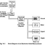
Signal Conditioning System: The measurand, which is basically a physical quantity, is detected by the first stage of the instrumentation or measurement system. The first stage is the detector transducer stage. The quantity is detected and converted … (Read More)
What is an Operational Amplifier? An Operational Amplifier is a dc amplifier having a high gain, of the order of 104 – 108. Such an amplifier can perform summing, integration, differentiation, or act as comparator with suitable feedback networks. Hence these … (Read More)
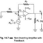
Closed Loop Gain of Non Inverting Amplifier: The circuit shown in Fig. 14.7 is commonly known as a Non-Inverting amplifier with feedback (or closed loop Gain Non-inverting amplifier), because it used a feedback and the input signal is applied to the … (Read More)
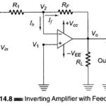
Negative Feedback Op Amp: The Inverting Amplifier configuration is shown in Fig. 14.8. The input signal is applied to the inverting terminal. The amplified inverted output is fed back to the inverting input through the resistor … (Read More)
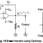
Integrator using Op Amp: An Integrator is a circuit that performs the mathematical operation of integration because it produces an output voltage that is proportional to the integral of the input. The Integrator using Op Amp is shown in Fig. 14.9. A … (Read More)
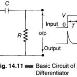
Differentiator using Op Amp: A Differentiator using Op Amp circuit that performs the mathematical operation of differentiation. It produces an output voltage proportional to slope of the input voltage. A common application of a differentiator is the detection of the leading … (Read More)
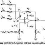
Summing Amplifier Circuit Diagram: Figure 14.17 shows an Summing Amplifier circuit diagram in inverting configuration with three inputs Va, Vb, Vc. Depending on the relation between Ra, Rb, Rc and RF, the circuit can be used as a Summing amplifier, Scaling amplifier … (Read More)
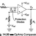
Op Amp Comparator Circuit: In the opamp applications discussed so far, the amplifiers use negative feedback. Under normal conditions, when negative feedback is used in such a circuit, the amplifier output voltage takes on values between … (Read More)
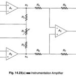
Instrumentation Amplifier Circuit: The schematic diagram of an Instrumentation Amplifier Circuit constructed with dc opamps and consisting of general features is shown in Fig. 14.23 (a). Many of the input specifications of the opamps employed directly determine the input specification of the … (Read More)
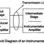
Instrumentation System Block Diagram: The measurement and control of physical conditions is very important in many industrial and consumer applications. For example, the operator may make necessary adjustments in the measurement of temperature or humidity inside a dairy … (Read More)
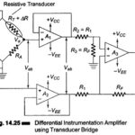
Differential Instrumentation Amplifier Transducer Bridge: Figure 14.25 shows a simplified circuit of a Differential Instrumentation Amplifier Transducer Bridge. In this circuit a resistive transducer (whose resistance changes as a function of some physical energy) is connected to one arm of the bridge. Let … (Read More)
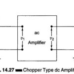
Chopper Type DC Amplifier: A simple ac amplifier Transformer may be used to amplify a dc input through the use of additional circuit component known as chopper. In this circuit, the dc signal is first converted into an ac signal, amplified … (Read More)
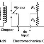
What is Electromechanical Chopper? An ac amplifier must see ac in order to perform useful work. A fair number of chopping and modulation techniques are available to change direct current, or to change very slowly varying signals into … (Read More)
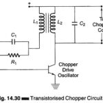
Self Oscillating Converter (Transistorized Chopper Circuit): A Transistorized dc to ac converter suitable for low level dc signal is illustrated in Fig. 14.30. The unique property of this assembly is that it starts to oscillate … (Read More)
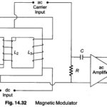
Magnetic Modulator: The most reliable substitutes for electromechanical choppers are magnetic modulators. These devices reach a null stability as low as 10 μV, but their response time is often less than 2 Hz and the ambient temperature range is restricted. The … (Read More)
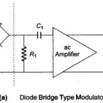
Diode Bridge Type Modulator with Transformer Coupling: Figure 14.33 shows a silicon diode ring modulator with an associated ac coupled dc amplifier. The amplifier itself has a gain of 65 db and a flat response within … (Read More)
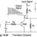
Transistor Chopper Circuit: A single transistor used as a dynamic switch to convert low level dc signal to an ac waveform is shown in Fig. 14.34. If the voltage applied to the transistor base is negative (in the … (Read More)
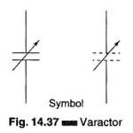
Varactor Diode Symbol: A specially processed junction diode that assumes the properties of a variable capacitor (about 5 – 250 pf) when its dc reverse voltage is varied is called a Varactor Diode shown in Fig. 14.37. This unique behavior can be … (Read More)
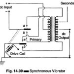
Synchronous Vibrator and Synchronous Chopper: Low dc current may be transformed into a high voltage dc by simple chopper action. Although an inductive type transformation process is required, the output dc may be obtained without rectifying devices. Figure 14.39 shows a … (Read More)
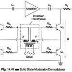
Solid State Modulator/Demodulator Circuit: A solid state modulator/demodulator circuit is shown in Fig. 14.41. The transformer T is driven by an ac source and couples each secondary connected to the two transistor pairs, Q1 – Q2 and Q3 – Q4. During the … (Read More)
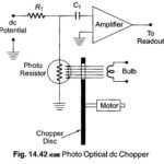
Photo Optical Modulator: The principle of an optical dc chopper is illustrated in Fig. 14.42. Devices of this type have been used widely in infrared signal detectors, whose output is a slowly varying dc product. The properties … (Read More)