Relay Timing Circuit:
An important characteristic of a relay is its time of operation. By the Relay Timing Circuit of operation is meant length of the time from the instant when the actuating element is energized to the instant when the relay contacts are closed. Sometimes it is desirable and necessary to control the operating time of a relay. For this purpose, mechanical accessories are used with relays.
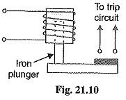
1. Instantaneous relay: An instantaneous relay is one in which no intentional time delay is provided. In this case, the relay contacts are closed immediately after current in the relay coil exceeds the minimum calibrated value. Fig. 21.10 shows an instantaneous solenoid type of relay. Although there will be a short time interval between the instant of pickup and the closing of relay contacts, no intentional time delay has been added. The instantaneous relays have operating time less than 0.1 second. The instantaneous relay is effective only where the impedance between the relay and source is small compared to the protected section impedance. The operating time of instantaneous relay is sometimes expressed in cycles based on the power-system frequency e.g. one-cycle would be 1/50 second in a 50-cycle system.
2. Inverse-time relay: An inverse-time relay is one in which the operating time is approximately inversely proportional to the magnitude of the actuating quantity. Fig. 21.11 shows the time-current characteristics of an inverse current relay. At values of current less than pickup, the Relay Timing Circuit never operates. At higher values, the time of operation of the relay decreases steadily with the increase of current. The inverse-time delay can be achieved by associating mechanical accessories with relays.
- In an induction relay, the inverse-time delay can be achieved by positioning a permanent magnet (known as a drag magnet) in such a way that relay disc cuts the flux between the poles of the magnet. When the disc moves, currents set up in it produce a drag on the disc which slows its motion.
- In other types of relays, the inverse time delay can be introduced by oil dashpot or a time-limit fuse. Fig. 21.12 shows an inverse time solenoid relay using oil dashpot. The piston in the oil dashpot attached to the moving plunger slows its upward motion. At a current value just equal to the pickup, the plunger moves slowly and time delay is at a maximum. At higher values of relay current, the delay time is shortened due to greater pull on the plunger.
The inverse-time characteristic can also be obtained by connecting a time-limit fuse in parallel with the trip coil terminals as shown in Fig. 21.13. The shunt path formed by time-limit fuse is of negligible impedance as compared with the relatively high impedance of the trip coil. Therefore, so long as the fuse remains intact, it will divert practically the whole secondary current of CT from the trip oil. When the secondary current exceeds the current carrying capacity of the fuse, the fuse will blow and the whole current will pass through the nip coil, thus opening the circuit breaker. The time-lag between the incidence of excess current and the tripping of the breaker is governed by the characteristics of the fuse. Careful selection of the fuse can give the desired inverse-time characteristics, although necessity for replacement after operation is a disadvantage.
3.Definite time lag relay: In this type of relay, there is a definite time elapse between the instant of pickup and the closing of relay contacts. This particular time setting is independent of the amount of current through the relay coil ; being the same for all values of current in excess of the pickup value. It may be worthwhile to mention here that practically all inverse-time relays are also provided with definite minimum time feature in order that the Relay Timing Circuit may never become instantaneous in its action for very long overloads.
Important Terms
It is desirable to define and explain some important terms much used in connection with relays.
1.Pick-up current: It is the minimum current in the relay coil at which the relay starts to operate. So long as the current in the relay is less than the pick-up value, the relay does not operate and the breaker controlled by it remains in the closed position. However, when the relay coil current is equal to or greater than the pickup value, the Relay Timing Circuit operates to energies the trip coil which opens the circuit breaker.
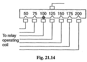
2.Current setting: It is often desirable to adjust the pick-up current to any required value. This is known as current setting and is usually achieved by the use of tappings on the relay operating coil. The taps are brought out to a plug bridge as shown in Fig. 21.14. The plug bridge permits to alter the number of turns on the relay coil. This changes the torque on the disc and hence the time of operation of the Relay Timing Circuit. The values assigned to each tap are expressed in terms of percentage full-load rating of C.T. with which the relay is associated and represents the value above which the disc commences to rotate and finally closes the trip circuit.
For example, suppose that an overcurrent relay having current setting of 125% is connected to a supply circuit through a current transformer of 400/5. The rated secondary current of C.T. is 5 amperes. Therefore, the pick-up value will be 25% more than 5 A i.e. 5 x 1.25 = 6.25 A. It means that with above current setting, the Relay Timing Circuit will actually operate for a relay coil current equal to or greater than 6.25 A.
The current plug settings usually range from 50% to 200% in steps of 25% for overcurrent relays and 10% to 70% in steps of 10% for earth leakage relays. The desired current setting is obtained by inserting a plug between the jaws of a bridge type socket at the tap value required.
3. Plug-setting multiplier (P.S.M.): It is the ratio of fault current in relay coil to the pick-up current i.e.
For example, suppose that a relay is connected to a 400/5 current transformer and set at 150%. With a primary fault current of 2400 A, the plug-setting multiplier can be calculated as under :
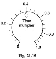
4. Time-setting multiplier: A relay is generally provided with control to adjust the time of operation. This adjustment is known as time-setting multiplier. The time-setting dial is calibrated from 0 to 1 in steps of 0.05 sec (see Fig. 21.15). These figures are multipliers to be used to convert the time derived from time/P.S.M. curve into the actual operating time. Thus if the time setting is 0.1 and the time obtained from the time/P.S.M. curve is 3 seconds, then actual relay operating time = 3 x 0.1 = 0.3 second. For instance, in an induction relay, the time of operation is controlled by adjusting the amount of travel of the disc from its reset position to its pickup position. This is achieved by the adjustment of the position of a movable backstop which controls the travel of the disc and thereby varies the tune in which the relay will close its contacts for given values of fault current. A so-called “time dial” with an evenly divided scale provides this adjustment. The actual time of operation is calculated by multiplying the time setting multiplier with the time obtained from time/P.S.M. curve of the relay.
Time/P.S.M. Curve:
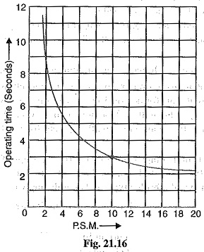
Fig. 21.16 shows the curve between time of operation and plug setting multiplier of a typical relay. The horizontal scale is marked in terms of plug-setting multiplier and represents the number of times the relay current is in excess of the current setting. The vertical scale is marked in terms of the time required for relay operation. If the P.S.M. is 10, then the time of operation (from the curve) is 3 seconds. The actual time of operation is obtained by multiplying this time by the time-setting multiplier.


