Hall Effect Relay Circuit:
Hall Effect Relay Circuit is utilized to give a phase comparator. The effect is very predominant in certain semiconductors such as indium arsenide, indium antimonide, indium phosphate, etc.
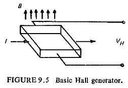
Figure (9.5) illustrates the basic Hall generator where the Hall crystal in the form of a slab carries current in the X-direction and is placed in a magnetic field in the Y-direction, a voltage known as Hall voltage is induced in the Z-direction across the edges of the crystal.
Let![]()
then the Hall voltage VH is given by
In the above expression white the first term on the right-hand side is a d.c. voltage proportional to the vectorial product of the two inputs—flux and current—the second term is an a.c. voltage of double frequency.
The double frequency term can be eliminated by cross connecting two Hall generators as shown in Fig. (9.6) where the two input signals are the sinusoidal a.c. currents I1 and I2.
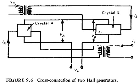
Assuming
fluxes through the crystals A and B are
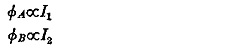
and current through the crystals are
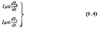
The two crystals are connected such that their output voltages oppose each other, and the resultant output of the combination is, therefore
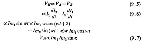
The device therefore now acts as a pure phase comparator. A telephone type relay can be directly operated from the Hall voltage. The Hall Effect Relay Circuit device does not require an auxiliary d.c. source while the transistorized circuits need about 10 V d.c. supply. The total volt-ampere consumption of the Hall device will be higher than transistor circuits. Its construction will be much simpler. Because of the high cost of the Hall crystal, large temperature error and low output, they have not yet been used in practical relays except in the U.S.S.R.
Gauss Effect Relays:
Some semiconductors have the property where resistance varies when magnetic field is applied. This effect is known as magneto resistivity or Gauss effect. If one a. c. voltage V1 produces the magnetic field through the crystal, which for the best results should be in the form of a disc having a large diameter and another voltage V2 sends a current radially through the disc, then the current will be proportional to V1V2 cos θ, where θ is the angle between the two voltages. This can thus act as a phase comparator and used as a static relay. This is however better than Hall Effect Relay Circuit devices because polarizing current is not required, the crystal is simpler and the output is higher. The cost of the crystal has limited its use in static relays.