Pin Diagram of 8250 UART:
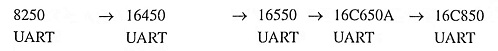
Pin Diagram of 8250 UART – The UART stands for Universal Asynchronous Receiver Transmitter. The UART is used in parallel-to-serial and serial-to-parallel conversions. Actually, UART receives data bytes from the computer and converts it into a single serial bitstream for outward transmission. During inward transmission of UART converts the serial bitstream into the bytes to feed into the computer. UARTs are available in different channels such as 1, 2, 4 and 8 channels. The single channel is represented by UART. DUART is a dual-channel UART and four channels of UART are represented by QUART. The eight channels of UART are called as octal of UART. The first PC UART, 8250, was manufactured by National Semiconductors. The evolution of UART ICs is given below:
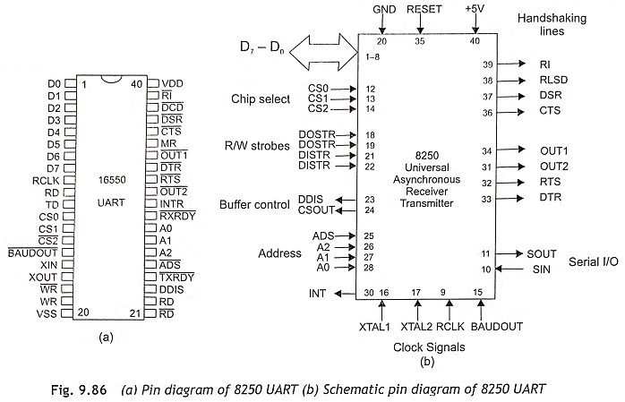
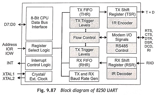
The pin diagram of 8050 is shown in Fig. 9.86(a) and its schematic pin diagram is depicted in Fig.9.86(b). The block diagram of 8250 UART is shown in Fig, 9.87.
Registers of 8250 UART
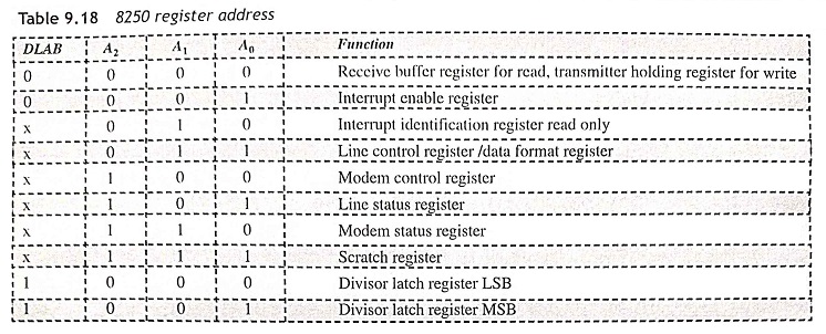
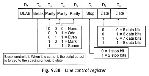
The 8250 UART has receive buffer register, transmitter holding register, interrupt enable register, interrupt identification register, line control register, modern control register, line status register, modem status register, scratch register, divisor latch register (LSB) and divisor latch register (MSB). Address signals A2, A1, A0 select a UART register for the CPU to read or write to during data transfer. The state of the divisor latch access bit (DLAB) is the most significant bit of the line control register as shown in Fig.9.88. Table 9.18 shows the addresses of 8250 registers.
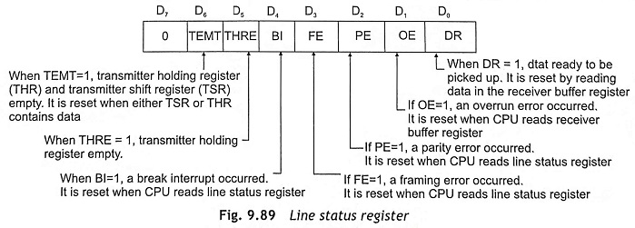
Line Status Register This register provides status information to the CPU concerning the data transfer. Figure 9.89 shows the function of bits of the line status register.
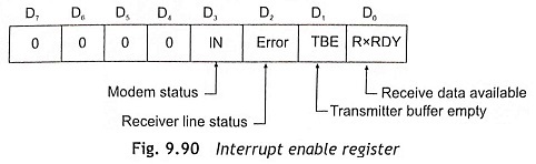
Interrupt Enable Register This register is to indicate modem status, receiver line status, transmitter buffer empty and receive data available as shown in Fig. 9.90.
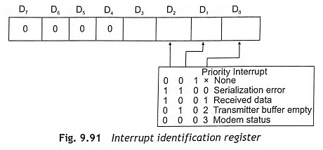
Interrupt Identification Register To provide minimum software overload during data character transfers, the UART prioritizes interrupts into four levels such as serialization error, received data, transmitter buffer empty and modem status as shown in Fig. 9.91.
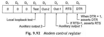
Modem Control Register This register controls the interfacing with the modem. The function of modem control register is depicted in Fig. 9.92.
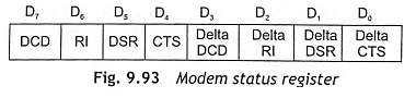
Modem Status Register This register provides the current states of the control lines from the modem to the CPU. Figure 9.93 shows the modem status register.
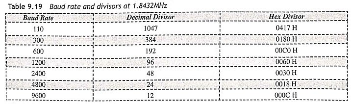
Divisor Register The baud rate generator is programmed with a divisor that computes the baud rate of the transmitter section. Table 9.19 shows the baud rate and divisors at 1.8432 MHz.
Transmitter
A transmitter is used for parallel-to-serial conversion and transmits data from CPU to the serial port. This section has transmit(TX) FIFO register and transmit shift register (TSR). The transmitter operates in non-FIFO and FIFO mode. Figure 9.94(a) shows the non-FIFO mode of transmitter and FIFO mode of transmitter is depicted in Figure 9.94(b).
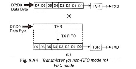
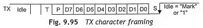
Initially, write data is sent to Transmit Holding Register (THR) and transmit data will be queued in TX FIFO. Then data is transferred to the Transmit Shift Register (TSR) and finally data is outputted from the transmitter. The TX character framing is done using start bit, data, stop bit and parity insertion as shown in Figure 9.95.
Receiver
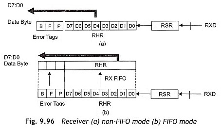
The receiver is used for serial-to-parallel conversion and received data from serial port to CPU. This has received (RX) FIFO and Receive Shift Register (RSR). The receiver can be operated in non-FIFO and FIFO mode as shown in Figure 9.96. The incoming data is received in the received shift register (RSR). Then the received data is queued in the RX FIFO. There error tags are associated with data in RHR which can be read through LSR. After that, Receive Holding Register (RHR) will be read data is outputted from the receiver.
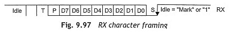
RX character validation is shown in Fig. 9.97. The high-to-low transition indicates a start bit. Start bit is validated if RX input is still low. During midbit sampling, the data, parity and stop bits are sampled at midbit. Line status errors are error tags and overrun error. Framing error exists if the stop bit is not detected. Parity error exists if the parity bit is incorrect. Break detected if RX input is LOW for duration of one character time. Overrun error exists if the character is received in RSR when RX FIFO is full.
UART Applications
UART is most commonly used in industry, telecom sector, automation, process control, remote access server, wireless applications, and entertainment systems as follows:
- Industry Building control, heating-ventilation-air-conditioning, security, telemetry, sensors, medical, testing and measurement, data terminals, video conference systems, photocopiers, printers, data recorder, and robot control, etc.
- Telecom Sector Network server management, hub, router, switch, console management, Bluetooth devices, keyboard-video-mouse switches and home networks, banking ATM, ticketing and vending, tolls collection systems, and car parking systems, etc.
- Automation and Process Control Processing, welding, printing and packaging, etc.
- Remote Access Server Modem servers and PC-based Internet-service-providers.
- Wireless Vehicle tracking, GPS, satellite, marine communication.
- Entertainment Set-top box, recreation and video-on-demand systems such as airplanes.