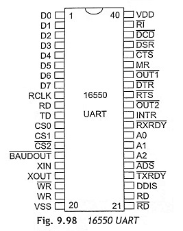
Pin diagram of 16550 UART:
The 16550 UART (Universal Asynchronous Receiver/Transmitter) is an integrated circuit which is used for the interfacing for serial communications. Usually, it is used to implement the serial port for personal computers and it is also used to connect to an RS-232C for modems, printers, and other peripheral devices. The 16550 UART was manufactured by National Semiconductors as shown in Fig. 9.98 and it has the following features:
→ The UART performs serial-to-parallel conversion on data received from modem and parallel-to-serial conversion on data received from the CPU using shift registers.
→ The UART has Modem control capability. The Modem control functions are CTS, RTS, DSR, DTR, RI, and DCD.
→ The UART can be operated in CHARACTER mode and FIFO mode. In FIFO mode, 16-bytes data to be stored in both receive and transmit modes.
→ It has fully programmable serial-interface characteristics such as
- 5-bit, 6-bit, 7-bit, and 8-bit characters
- Even, odd, or no-parity bit generation and detection
- 1-bit . 11/2 -bit and 2-stop bit generation
→ A programmable baud generator divides the input clock by 1 to (216-1) and generates a 16 x clock.
→ False start bit detection, line break generation and detection
→ Independently controlled transmit, receive, line status, and data set interrupts.
→ The UART has complete status reporting capability.
→ Internal diagnostic capabilities such as loopback controls for communications link fault isolation and break, parity, overrun and framing error simulation.
→ UART has a processor interrupt system. Interrupts can be programmed as per programmer requirements.
In the FIFO mode, transmitter and receiver are buffered with 16-byte FIFO’s to reduce the number of interrupts. In 16550 UART, asynchronous serial data are transmitted and received without any clock signal.
There are two separate sections of transmitters and receive for data communications. The transmitter and the receiver can work independently and the 16550 operates in simplex, half-duplex and full-duplex modes.
The 16550 UART provides different registers such as Transmit Holding Register (THR), Receive Holding Register (RHR), Interrupt Enable Register (IER), Interrupt Status Register (ISR), FIFO Control Register (FCR), Line Control Register (LCR), Modem Status Register (MSM) and Scratch Pad Register (SPR):
- THR The THR (Transmit Holding Register) is a write-only type register and its function is that loads data to be transmitted into TX FIFO.
- RHR The RHR (Receive Holding Register) is a read-only type register and its function is that reads out received data from the RX FIFO.
- IER The IER (Interrupt Enable Register) is a read/write type register and it is used to enable or disable interrupts.
- ISR The ISR (Interrupt Status Register) is a read-only type register and it can be used for highest priority pending interrupt.
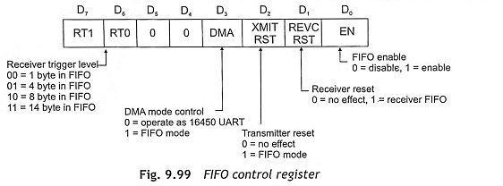
- FCR The FCR (FIFO Control Register) is a write-only type register. The FIFO control register is used to enable the transmitter and receiver FIFOs. It clears the transmitter and receiver FIFOs and generates control for the 16550 interrupts. The transmitter and receiver are independently controlled. Set the RCVR FIFO trigger level and select the type of DMA signal. Figure 9.99 shows the FIFO control register.
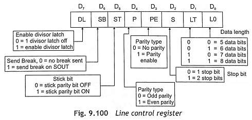
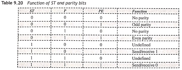
- LCR The LCR (Line Control Register) ) is a read/write type register. This register holds the number of data bits (word length), stop bit length, parity selection and break. Figure 9.100 shows the line control register, and the function of Stick Bit (ST) and parity bits is illustrated in Table 9.20.
- MSR The MSR(Modem Status Register) is a read-only type register . This is used to store the state of modem inputs CD, RI, DSR, CTS and state changes since last read.
- SPR The SPR(Scratch Pad Register) is a read/write type register. This is used as a general-purpose read/write register.
- DLL and DLM These are read/write type registers and used as 16-bit divisors for the internal baud rate generator where DLL is LSB and DLM is MSB.
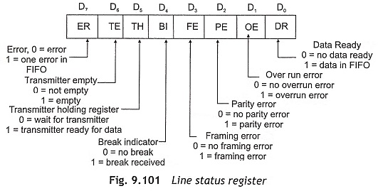
- Line Status Register This register provides status information to the CPU related with the data transfer. Figure 9.101 shows the line status register.
Programmable Baud Rate Generator The UART consists of a programmable baud rate generator. The baud rate is the number of bits transferred per second including the start, data, parity and stop bits. The baud rate generator is programmed with a divisor and computes the baud rate. The input clock frequency is dc to 24 MHz which can be divided by any divisor from 2 to 216– 1. The output frequency of the baud generator is 16 x baud. The 8-bit latches are used to store the divisor in a 16-bit binary format.