Parallel Operation of Transformer:
When the load outgrows the capacity of an existing transformer, it may be economical to install another one in parallel with it rather than replacing it with a single larger unit. Also, sometimes in a new installation, two units in parallel, though more expensive, may be preferred over a single unit for reasons of reliability half the load can be supplied with one unit out. Further, the cost of maintaining a spare is less with two units in parallel. However, when spare units are maintained at a central location to serve transformer installations in a certain region, single-unit installations would be preferred. It is, therefore, seen that Parallel Operation of Transformer is quite important and desirable under certain circumstances.
The satisfactory and successful operation of transformers connected in parallel on both sides requires that they fulfill the following conditions:
(i) The transformers must be connected properly as far as their polarities are concerned so that the net voltage around the local loop is zero. A wrong polarity connection results in a dead short circuit.
(ii) Three-phase transformers must have zero relative phase displacement on the secondary sides and must be connected in a proper phase sequence. Only the transformers of the same phase group can be paralleled. For example, Y/Y and Y/Δ transformers cannot be paralleled as their secondary voltages will have a phase difference of 30°. Transformers with +30° and -30° phase shift can, however, be paralleled by reversing the phase-sequence of one of them.
(iii) The transformers must have the same voltage-ratio to avoid no-load circulating current when transformers are in parallel on both primary and secondary Since the leakage impedance is low, even a small voltage difference can give rise to considerable no-load circulating current and extra I2R loss.
(iv) There should exist only a limited disparity in the per-unit impedances (on their own bases) of the transformers. The currents carried by two transformers (also their kVA loadings) are proportional to their ratings if their ohmic impedances (or their pu impedances on a common base) are inversely proportional to their ratings or their per unit impedances on their own ratings are The ratio of equivalent leakage reactance to equivalent resistance should be the same for all the transformers. A difference in this ratio results in a divergence of the phase angle of the two currents, so that one transformer will be operating with a higher, and the other with a lower power factor than that of the total output; as a result, the given active load is not proportionally shared by them.
Parallel Operation of Transformer under No Load:
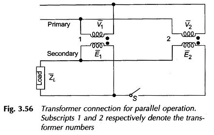
The Parallel Operation of Transformer can be easily conceived on a per phase basis. Figure 3.56 shows two transformers paralleled on both sides with proper polarities but on no-load. The primary voltages V1 and V2 are obviously equal. If the voltage-ratio of the two transformers are not identical, the secondary induced emf s, E1 and E2 though in phase will not be equal in magnitude and the difference (E1 – E2) will appear across the switch S. When secondaries are paralleled by closing the switch, a circulating current appears even though the secondaries are not supplying any load. The circulating current will depend upon the total leakage impedance of the two transformers and the difference in their voltage ratios. Only a small difference in the voltage-ratios can be tolerated.
Division of Load between Transformers in Parallel:
Equal voltage-ratios:
When the transformers have equal voltage ratio, E1 = E2 in Fig. 3.56, the equivalent circuit of the two transformers would then be as shown in Fig. 3.57 on the assumption that the exciting current can be neglected in comparison to the load current. It immediately follows from the sinusoidal steady-state circuit analysis that
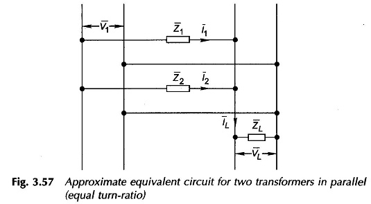
Taking VL as the reference phasor and defining complex power as V * I, the multiplication of VL on both sides of Eqs. (3.83) and (3.84) gives
These are phasor relationships giving loadings in the magnitude and phase angle. Equations (3.86) and (3.87) also hold for pu loads and leakage impedances if all are expressed with reference to a common base. It is seen from Eqs. (3.83) and (3.84) that the individual currents are inversely proportional to the respective leakage impedances. Thus, if the transformers are to divide the total load in proportion to their kVA ratings, it is necessary that the leakage impedances be inversely proportional to the respective kVA ratings, i.e.
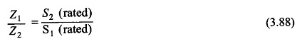
This condition is independent of the power factor of the total load. The condition of Eq. (3.88) can be written as
![]()
It means that if individual transformer loadings are to be in the ratio of their respective kVA ratings, their pu impedances (on their own ratings) should be equal. If
![]()
the transformer 1 will be the first to reach its rated loading as the total kVA load is raised. The maximum permissible kVA loading of the two in parallel without overloading any one is then given by
![]()
Unequal Voltage-ratios:
It has already been mentioned that a small difference in voltage ratios can be tolerated in the Parallel Operation of Transformer. Let E1 and E2 be the no-load secondary emfs of two transformers in parallel. With reference to Fig. 3.56, if a load current IL is drawn at voltage VL, two mesh voltage balance equations can be written as
![]()
On no-load IL = 0, so that the circulating current between the two transformers is given by
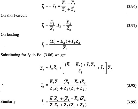
Normally E1 and E2 are in phase or their phase difference is insignificant. Severe results of paralleling transformers not belonging to the same phase-groups (say Y/Y and Y/Δ transformers) are immediately obvious from Eq. (3.96) for no-load circulating current. When many transformers are in parallel, their load sharing can be found out using the Millman theorem.