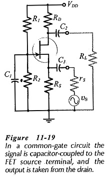
Common Gate Circuit
Common Gate Circuit: The FET Common Gate Circuit (CG) shown in Fig. 11-19 uses voltage divider bias. The ac output is taken from the drain terminal, and an external load (RL) is capacitor-coupled to the…
Common Emitter Amplifier Circuit: Consider the Common Emitter Amplifier Circuit circuit shown in Fig. 6-17. When the capacitors are regarded as ac short-circuits, it is seen that the circuit input terminals are the transistor base…
Common Drain JFET Amplifier or Source Follower: In the Common Drain JFET Amplifier circuit (also called the source follower), the output voltage is developed across source resistor RS. External load resistor RL is connected to…
Common Drain Amplifier Circuit Diagram: The FET Common Drain Amplifier Circuit Diagram shown in Fig. 11-14 has the output voltage developed across the source resistor (RS). The external load (RL) is capacitor-coupled to the source…
Common Collector Circuit Analysis: In the Common Collector Circuit Analysis (CC) shown in Fig. 6-28 the external load (RL) is capacitor-coupled to the transistor emitter terminal. The circuit uses voltage divider bias to derive the transistor…
Common Collector Characteristics of BJT: In the Common Collector Characteristics of BJT circuit arrangement of Fig. 4-31, the collector terminal is common to both input CB voltage and output CE voltage. Using this circuit, the…
Common Base Transistor Characteristics: To investigate the Common Base Transistor Characteristics of a diode (a two-terminal device), several levels of forward or reverse bias voltage are applied and the resulting current levels are measured. The…
Common Base Circuit Diagram: The Common Base Circuit Diagram (CB) shown in Fig. 6-34 is very similar to a CE circuit, except that the input signal is applied to the transistor emitter terminal (via C2),…
Combined Operation of Power Plants Interview Questions and Answers: 1. Why is it necessary to operate hydro and steam plants in combination ? Ans. It is necessary to operate hydro and steam plants in combination…
Combinational Circuit | Block Diagram | Design Procedure: When logic gates are connected together to produce a specified output for certain specified combinations of input variables, with no storage involved, the resulting circuit is called…