Key Diagram of Substation 66/11KV:
Fig. 25.10 shows the key diagram of a typical 66/11 kV sub-station. The Key Diagram of Substation can be explained as under:
1. There are two 66 kV incoming lines marked ‘incoming 1’ and ‘incoming 2’ connected to the bus-bars. Such an arrangement of two incoming lines is called a double circuit. Each incoming line is capable of supplying the rated sub-station load. Both these lines can be loaded simultaneously to share the sub-station load or any one line can be called upon to meet the entire load. The double circuit arrangement increases the reliability of the system. In case there is a breakdown of one incoming line, the continuity of supply can be maintained by the other line.
2. The sub-station has duplicate bus-bar system; one ‘main bus-bar’ and the other spare bus- The incoming lines can be connected to either bus-bar with the help of a bus-coupler which consists of a circuit breaker and isolators. The advantage of double bus-bar system is that if repair is to be carried on one bus-bar, the supply need not be interrupted as the entire load can be transferred to the other bus.
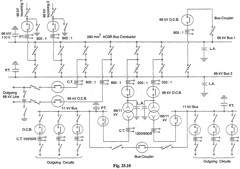
3. There is an arrangement in the sub-station by which the same 66 kV double circuit supply is going out i.e. 66 kV double circuit supply is passing through the sub-station. The outgoing 66 kV double circuit line can be made to act as incoming line.
4. There is also an arrangement to step down the incoming 66 kV supply to 11 kV by two units of 3-phase transformers; each transformer supplying to a separate bus-bar. Generally, one transformer supplies the entire sub-station load while the other transformer acts as a standby If need arises, both the transformers can be called upon to share the sub-station load. The 11 kV outgoing lines feed to the distribution sub-stations located near consumers localities.
5. Both incoming and outgoing lines are connected through circuit breakers having isolators on their either end. Whenever repair is to be carried over the line towers, the line is first switched off and then earthed.
6. The potential transformers (P.T.) and current transformers (C.T.) and suitably located for supply to metering and indicating instruments and relay circuits (not shown in the figure). The P.T. is connected right on the point where the line is terminated. The CTs are connected at the terminals of each circuit breaker.
7. The lightning arresters are connected near the transformer terminals (on H.T. side) to protect them from lightning strokes.
8. There are other auxiliary components in the sub-station such as capacitor bank for power factor improvement, earth connections, local supply connections, d.c. supply connections However, these have been omitted in the Key Diagram of Substation for the sake of simplicity.
Key Diagram of 11kv/400v Indoor Substation:
Fig. 25.11 shows the Key Diagram of Substation of a typical 11 kV/400 V indoor sub-station. The key diagram of this sub-station can be explained as under:
1. The 3-phase, 3-wire 11 kV line is tapped and brought to the gang operating switch installed near the sub-station. The G.O. switch consists of isolators connected in each phase of the 3-phase line.
2. From the G.O. switch, the 11 kV line is brought to the indoor sub-station as underground cable. It is fed to the H.T. side of the transformer (11 kV/400 V) via the 11 kV O.C.B. The transformer steps down the voltage to 400 V, 3-phase, 4-wire.
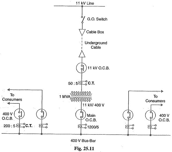
3. The secondary of transformer supplies to the bus-bars via the main O.C.B. From the bus-bars, 400 V, 3-phase, 4-wire supply is given to the various consumers via 400 V O.C.B. The voltage between any two phases is 400 V and between any phase and neutral it is 230 V. The single phase residential load is connected between any one phase and neutral whereas 3-phase, 400 V motor load is connected across 3-phase lines directly.
4. The CTs are located at suitable places in the sub-station circuit and supply for the metering and indicating instruments and relay circuits.