Frequency Domain Network Function:
As the frequency domain network function is a complex function, it can be expressed mathematically in two ways i.e. using rectangular coordinates or using polar coordinates.
In rectangular coordinates it can be written as,
![]()
R(ω) = Re[H(jω)] = Real part of network function
X(ω) = Imj [H(jω)] = Imaginary part of network function
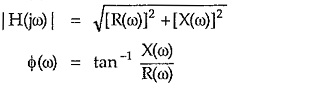
While in polar coordinates H(jω) can be written as,
![]()
|H(jω)| = Magnitude of the network function
Φ(ω) = Angle of the network function
The equations (1) and (2) are related to each other as,
Sometimes the magnitude |H(jω)| is denoted as MR while the angle of H(jω) is denoted as ΦR so polar representation is expressed as,
![]()
where
MR = Resultant magnitude which is function of ω
ΦR = Resultant phase angle which is function of ω
Thus R(ω), X(ω) are the parts of network function in the rectangular coordinates while MR and ΦR are the parts of network function in the polar coordinates.
The frequency response means to sketch the variations in the various parts of the network function as the ω is changed from 0 to ∞. The use of polar coordinates is very common to obtain the frequency response. These parts of network function play an important role in network design because,
- Most of the times, the specifications for which the networks are to be designed, are given interms of magnitude and phase. The real and imaginary parts are rarely used to describe the required specifications.
- The measurement of these parts of the network functions is easy due to availability of the instruments like C.R.O., voltmeters, ammeters, wattmeters etc.