Circuit Model of DC Machine:
The parallel paths of DC machine armature are symmetrical and each has an induced emf Ea and a resistance Rp. The armature can be represented by the Circuit Model of DC Machine with voltage Ea and a series resistance as shown in Fig. 7.5.
![]()
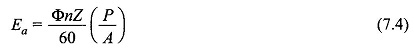
The armature resistance is quite small so as to limit the copper-loss to an acceptable value. Figure 7.5 also shows the field Circuit Model of DC Machine of and the field coil axis is placed at 90° to the brush axis as per the actual arrangement in the machine. From circuit point of view it is not necessary to rigidly follow this scheme. Since most of the time steady-state dc behaviour of the machine will be considered, the inductances of field and of armature (this is negligible any way) circuits are of no consequence and are not shown in the Circuit Model of DC Machine. The armature induced emf and machine torque are governed by the relationships of Eqs (7.4) and (7.8).
![]()
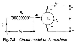
The voltage drop at brush-commutator contact is fixed (1-2 V), independent of armature current as the conduction process is mainly through numerous short arcs. However, this voltage being small is modelled as linear resistance and lumped with Ra. From now onwards it will be assumed that Ra includes the effect of brush voltage drop.
Generating Mode of DC Machine:
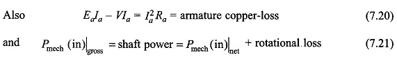
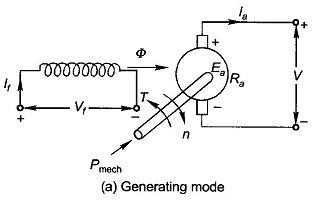
The machine operates in generating mode (puts out electrical power) when Ia is in the direction of induced emf Ea as in Fig. 7 6(a). For the armature circuit
![]()
The mechanical power converted to electrical form is
![]()
The net electrical power output is
![]()
In this mode torque (T) of electromagnetic origin is opposite to the direction of rotation of armature, i.e., mechanical power is absorbed and a prime-mover is needed to run the machine.
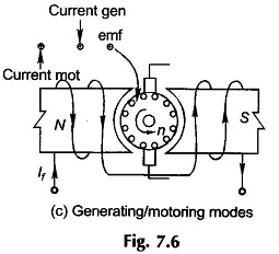
The conductor emf and current are also in the same direction for generating mode as shown in the cross-sectional view of Fig. 7.6(c).
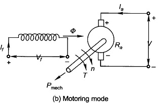
Motoring Mode of DC Machine:
In this mode, la flows in opposition to induced emf Ea as in Fig. 7.6(b). Ea is now known as the back emf to stress the fact that it opposes the armature emf. For the armature circuit
![]()
The electrical power converted to mechanical form is
![]()
The electrical power input is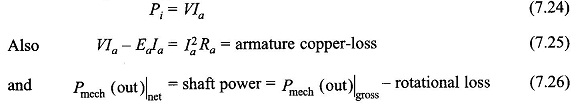
In this mode torque (T) of electromagnetic origin is in the direction of armature rotation, i.e., mechanical power is put out and is absorbed by load (mechanical).
Conductor emf and current are also in opposite directions for motoring mode as shown in Fig. 7.6(c).