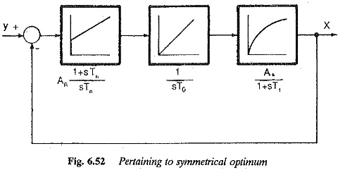
Control Techniques for Electric Drives

Symmetrical Optimum

Symmetrical Optimum: Symmetrical Optimum – Sometimes automatic control systems contain integrating also besides first order delay elements, proportional elements and deadzones. Such a system when compensated on the basis of magnitude optimum discussed in the previous sections will become oscillatory with zero damping. As has already been explained the magnitude optimum utilizes a PI controller to […]

Symmetrical Optimum Read More »

Uncompensated Large Time Constants

Uncompensated Large Time Constants: It is possible to compensate only one Uncompensated Large Time Constants using a PI controller. A PID controller is used to compensate for two large time constants. On technical grounds, compensation of more than two constants using a PID Therefore if a transfer function has more than two dominant poles, only

Uncompensated Large Time Constants Read More »

Controller Transfer Function

Controller Transfer Function: While a Controller Transfer Function is designed to improve the behavior of a given control system in practice it is very difficult to realize such a controller because of the availability of components. The actual time constant of the controller may deviate from the theoretically designed value. Also the operating conditions may

Controller Transfer Function Read More »

Phase Margin Optimum

Phase Margin Optimum: The method can be based on the phase margin in which the controller is designed to provide a minimum phase margin. The design makes use of Bode plots. The ratio of time constants can be decided depending upon the phase margin required, which directly influences the damping. Therefore this method has an

Phase Margin Optimum Read More »

Magnitude Optimum

Magnitude Optimum: The design of a controller based on the principle Magnitude Optimum that it allows all the fre­quencies to pass through in a similar way for a simple system is shown in Fig. 6.31. The system has an input R(s) and output C(s). The closed loop transfer function The plant transfer function Gp(s) is assumed

Magnitude Optimum Read More »

Controller Design Frequency Response

Controller Design Frequency Response: The Controller Design Frequency Response (or root locus) alters or reshapes the frequency response (or root locus) of the original system to the desired one. Thus the ideal goal of compensation is to achieve a control system which has a desired performance, viz. having zero steady- state error, optimised dynamic performance,

Controller Design Frequency Response Read More »

Methods of Compensation in Control System

Methods of Compensation in Control System: The Different Methods of Compensation in Control System are Cascade Compensation Feedback Compensation Load Circuit Compensation Input Circuit Compensation A drive system having closed loop control may not be satisfactory with regard to its stability characteristics, speed of response and steady-state accuracy. The system may be oscillatory or even

Methods of Compensation in Control System Read More »

Control System Performance

Control System Performance: From the foregoing discussion on control systems it can be seen that the be­haviour of the control systems can be specified, based on several time domain specifications. To provide a basis for comparison of several types of control and solution, the performance indices are defined. These help as a quantita­tive measure of

Control System Performance Read More »

Scroll to Top