Band Reject Filter Circuit:
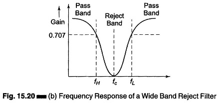
In this Band Reject Filter Circuit, frequencies are attenuated in the stop band and passed outside it, as shown in Fig. 15.20(b). As with band pass filters, band reject filters can also be classified as (i) wide and (ii) narrow band.

The narrow band reject filter circuit is also called the notch filter. Because of its higher Q which is greater than 10, the bandwidth of the narrow band reject filter is much smaller than that of the wide band reject filter. The band reject filter is also called a band stop or band elimination filter because it eliminates a certain band of frequencies.
Wide Band Reject Filter:
Figure 15.20 (a) shows wide band reject filter circuit using a low pass filter, a high pass filter and a summing amplifier. For a proper band reject response, the low cutoff frequency fL of the high pass filter must be larger than the high cutoff frequency fH of the low pass filter. Also, the pass band gain of both high pass and low pass sections must be equal.
Narrow Band Reject Filter:
The narrow band reject filter, often called the notch filter, is commonly used for the attenuation of a single frequency. For example, it may be necessary to attenuate 60 Hz or 400 Hz noise or hum signals in a circuit. The most commonly used notch filter is the Twin T network, shown in Fig. 15.21(a), which is a passive filter composed of two T shaped networks.
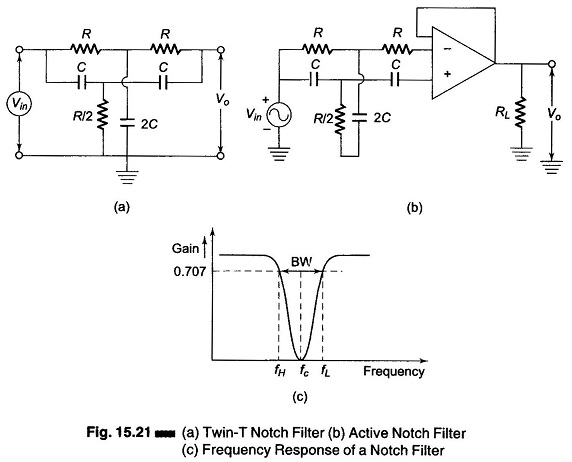
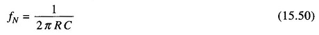
One T network is made up of two resistors and a capacitor, while the other is made of two capacitors and a resistor. The frequency at which maximum attenuation occurs is called the notch-out frequency, given by
One disadvantage of the passive twin T network is that it has a relatively low figure of merit, Q. As discussed earlier, the higher the value of Q, the more selective is the filter. Therefore, to increase the Q of the twin T network significantly, it should be used with a voltage follower, as shown in Fig. 15.21(b). Figure 15.21(c) shows the frequency response of a notch filter.
The Notch filters are used in communications, biomedical instruments, etc. where the elimination of certain frequencies is necessary.