Three Phase Bridge Inverter | Working Principle:
The basic three phase bridge inverter is a six-step inverter. A step is defined as a change in the firing sequence. A 3-phase thyristor bridge-inverter is shown in Fig. 11.49. Th1 to Th6 are the six load-carrying thyristors while D1 to D6 are the free-wheeling diodes. Each pair of thyristors in a branch (Th1 and Th4; Th2 and Th5; Th3 and Th6) are gated for T/2 and are out-of-phase with each other, i.e. they are never gated simultaneously. Th1, Th2 and Th3 are fired out-of-phase progressively by 120° and so are Th4, Th5 and Th6. This is a must to obtain three output voltages out-of-phase 120°.
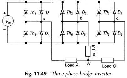
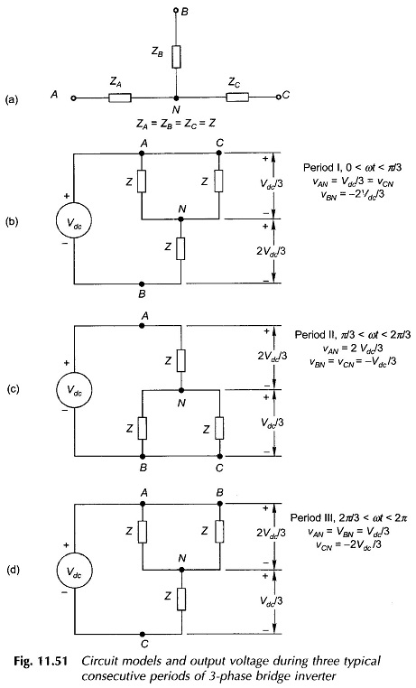
Figure 11.50 shows the conducting periods of various thyristors as per the firing sequence indicated above. Over an angle of 2π, six periods (one-sixth of each cycle period) are recognized and the thyristors conducting in these periods are identified. It is noticed that in any one period only three thyristors are conducting. The frequency of firing is six times the output frequency. The circuit models during three typical consecutive periods corresponding to the positive half-cycle of vAN are drawn in Fig. 11.51 and the output voltages in terms of the input dc voltage (Vdc) are determined.
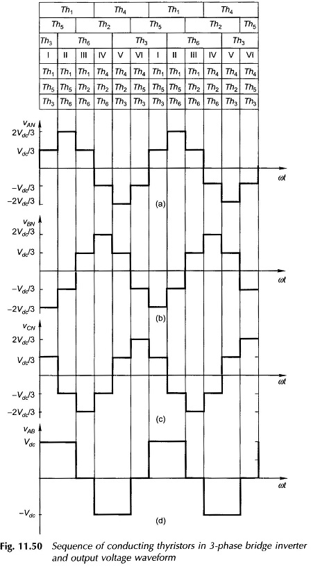
The voltage waveforms for three phase-to-neutral voltages of the three phase bridge Inverter of Fig. 11.49 can be easily drawn by this procedure. It is immediately obvious that these voltages are out-of-phase by 120°. The phase sequence can be reversed by simply reversing the sequence of firing the thyristors. The line-to-line voltages are found by taking the difference of phase voltages. The waveform of vAB=vAN-vBN is illustrated in Fig. 11.50(d). It is also easily seen that the fundamental components of line-to-line (or phase-to-neutral) voltages form a balanced set. The free-wheeling diodes permit currents to flow which are out-of-phase with these voltages.