Series Resistance Microammeter:
High d.c. voltages are usually measured by connecting a very high resistance (few hundreds of megaohms) in Series Resistance Microammeter as shown in Fig. 7.1.
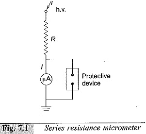
Only the current I flowing through the large calibrated resistance R is measured by the moving coil microammeter. The voltage of the source is given by
![]()
The voltage drop in the meter is negligible, as the impedance of the meter is only few ohms compared to few hundred mega-ohms of the series resistance R. A protective device like a paper gap, a neon glow tube, or a zener diode with a suitable series resistance is connected across the meter as a protection against high voltages in case the series resistance R fails or flashes over. The ohmic value of the series resistance R is chosen such that a current of one to ten microamperes is allowed for full-scale deflection. The resistance is constructed from a large number of wire wound resistors in series. The voltage drop in each resistor element is chosen to avoid surface flashovers and discharges. A value of less than 5 kV/cm in air or less than 20 kV/cm in good oil is permissible. The resistor chain is provided with corona free terminations. The material for resistive elements is usually a carbon-alloy with temperature coefficient less than 104/°C. Carbon and other metallic film resistors are also used. A resistance chain built with ±1% carbon resistor located in an airtight transformer oil filled P.V.C. tube, for 100 kV operation had very good temperature stability. The limitations in the Series Resistance Microammeter design are:
- power dissipation and source loading,
- temperature effects and long time stability,
- voltage dependence or resistive elements, and
- sensitivity to mechanical stresses.
Series Resistance Microammeter are built for 500 kV d.c. with an accuracy better than 0.2%.
Resistance Potential Divider for DC Voltage:
A resistance potential divider with an electrostatic or high impedance voltmeter is shown in Fig. 7.2. The influence of temperature and voltage on the elements is eliminated in the voltage divider arrangement. The high voltage magnitude is given by [(R1 +R2)/R2] v2, where v2 is the d.c. voltage across the low voltage arm R2. With sudden changes in voltage, such as switching operations, flashover of the test objects, or source short circuits, flashover or damage may occur to the ground capacitances. To avoid these transient voltages, voltage controlling capacitors are connected across the elements.
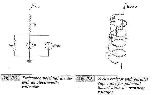
A corona free termination is also necessary to avoid unnecessary discharges at high voltage ends. A Series Resistance Microammeter with a parallel capacitor connection for linearization of transient potential distribution is shown in Fig. 7.3. Potential dividers are made with 0.05% accuracy up to 100 kV, with 0.1% accuracy up to 300 kV, and with better than 0.5% accuracy for 500 kV.