RF Signal Generator:
An RF signal generator, when used for alignment and testing of the RF and IF stages of a TV receiver, permits recording of circuit performance at one frequency at a time. Therefore, plotting the total response curve point by point over the entire channel bandwidth becomes a laborious process and takes a long time. To overcome this difficulty, a special RF signal generator, known as a sweep generator, is used. It delivers RF output voltage at a constant amplitude which sweeps across a range of frequencies and continuously repeats at a predetermined rate.
The Sweep Frequency Generator is designed to cover the entire VHF and UHF range. Any frequency can be selected as the centre frequency by a dial on the front panel of the instrument.
Sweep Frequency Generator is obtained by connecting a varactor diode across the HF oscillator circuits. A modified triangular voltage at 50 Hz is used to drive the varactor diode. Thus the frequency sweeps on either side of the oscillator centre frequency, at the rate of driving voltage frequency. The amplitude of the driving voltage applied across the varactor diodes can be varied to control maximum frequency deviation on either side of the carrier frequency. This is known as the sweep width and can be adjusted to the desired value, up to a maximum of about ± 15 MHz. A width control is provided for this procedure.
Alignment Procedure:
The output of the TV Sweep Generator is connected to the input terminals of the tuned circuit under test.
The frequency and sweep width dials are adjusted to a sweep range which lies in the pass-band of the circuit. With an input signal of constant amplitude, the output voltage varies in accordance with the frequency gain characteristics of the circuit. The magnitude of the output voltage varies with time as the oscillator frequency sweeps back and forth through the centre frequency.
The RF output is detected either by a video detector in the receiver or by a demodulator probe. The detected output varies at the sweep rate of 50 Hz and its instantaneous amplitude changes in accordance with the circuit characteristics. Thus the output signal is a low frequency signal at 50 Hz and can be displayed on an ordinary scope, provided the low frequency response of the vertical amplifier is flat, down to at least 50 Hz.
In order to obtain a linear display of the detected signal on the CRO, the scope sweep voltage must vary accordingly and have a frequency of 50 Hz.
The basic circuit configuration used for the alignment of any tuned circuit with a sweep generator and scope is shown in Fig. 8.11.
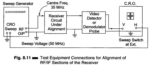
The time base switch of the CRO is set on External and its horizontal input terminals are connected to the sweep output on the sweep generator. Thus, the application of a 50 Hz triangular voltage to the horizontal deflecting plates results in a linear display on the scope screen, both during trace and retrace periods.