Relays Definition:
The main purpose of a PLC is to replace real world relays. A Relays Definition is basically an electro-magnetic switch. When a voltage is applied to the coil, a magnetic field is generated. This magnetic field attracts the contact of the relay in, causing them to make a connection. These contacts act like a switch and allow current to flow between 2 points thereby closing the circuit.
Let us consider the following example in which we will simply turn ON a bell, whenever the switch is closed. A switch, relay and a bell is connected as shown in Fig. 21.28.
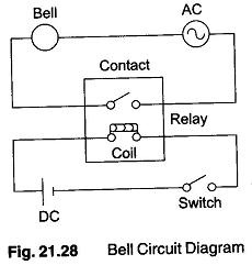
When the switch closes, current is applied to a bell causing it to sound. In Fig. 21.28, it is seen that it consists of two separate circuits. One circuit is the dc part and the other circuit is the ac part.
In this case we are using a dc relay to control an ac circuit. When the switch is open, no current flows through the coil of the relay. As soon as the switch is closed, current starts to flow through the coil causing a magnetic field to build up. This magnetic field causes the contacts of the relay to close. Hence, ac current flows through the bell and the sound of the bell can be heard.
Let us now replace the Relays Definition by a PLC. The first process is necessary to create what is called a ladder diagram. (A ladder diagram consists of vertical lines called the bus bars and within these vertical lines are placed various horizontal lines consisting of input contacts and output. These horizontal lines are called as rungs.) We have to create a ladder diagram, but a PLC does not understand a schematic diagram. It only recognizes code. Fortunately most PLCs have software which convert ladder diagrams into code.
First step: We have to translate all of the items we are using into symbols the PLC understands. The PLC does not understand terms like switch, relay, bell etc. It prefers input, output, coil, contact, etc. It does not care what actual input or output device actually is. It only cares that it is an input or an output.
The batteries or power supply is replaced by a symbol. This symbol is common to all ladder diagrams. These are called the bus bars. These look like two vertical lines on either side and the input and output are placed within these bars. The left side can be considered as the voltage and the right side as the ground and the current flow from left to right.
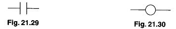
The inputs and outputs each are also given a symbol. The input, that is, the switch will be connected by a symbol, shown in Fig. 21.29. This symbol can also be used as the contact of the Relays Definition.
Only one output is normally used, e.g. a bell. The output that the bell will be physically connected in the circuit by the symbol is shown in Fig. 21.30. This symbol is used as the coil of a relay.
The ac supply is an external supply hence it is not put in the ladder diagram. The PLC only knows and cares about which output it has to turn on.
The PLC must know where everything is located. In other words we have to give all the devices an address. The location where the switch is going to be physically connected to the PLC. Each inputs and outputs used have an address. The PLC has a lot of inputs and outputs but the PLC has to figure out which device is connected where.
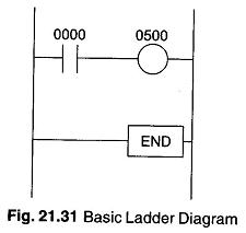
The final step is to convert the schematic into a logical sequence of events. The program written tells the PLC what to do when certain events take place. The PLC should be told what to do when the operator turns ON the switch. The diagram shown in Fig. 21.31 is the final converted diagram. In Fig. 21.31, the input is called as ‘0000’ and output is called as ‘0500’.