Precision Full Wave Rectifier:
The Precision Full Wave Rectifier circuits accept an ac signal at the input, inverts either the negative or the positive half, and delivers both the inverted and noninverted halves at the output, as shown in the Fig. 2.62.
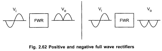
The operation of the positive full wave rectifier is expressed as
![]()
and that of the negative rectifier as
![]()
Looking at equations 1 and 2 we can say that Precision Full Wave Rectifier circuits are precision absolute value circuits. Fig. 2.63 shows a full wave rectifier or absolute value circuit.
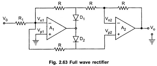
CASE 1 : Vi > 0 : When Vi > 0, inverting side of A1 will force its output to swing negative, thus forward biasing D1 and reverse biasing D2. Since no current flows through resistance R connected between Vn1 and Vp2, both are equipotential
![]()
The Fig. 2.64 shows the equivalent circuit.
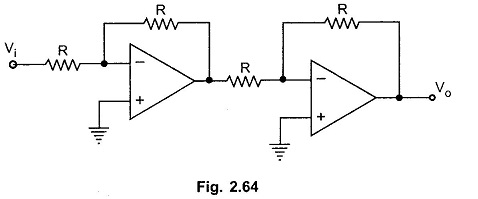
From equivalent circuit, the output voltage can be given
CASE 2 : Vi < 0 : When Vi < 0, negative, the output voltage of A1 swings to positive, making diode D1 reverse biased and diode D2 forward biased.
The Fig. 2.65 shows the equivalent circuit.
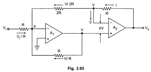
Let the output voltage of op-amp A1 be V. Since the differential input to A2 is zero, the inverting input terminal is also at voltage V, as shown in the Fig. 2.65.
Applying KCL at node ‘a’ we have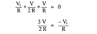
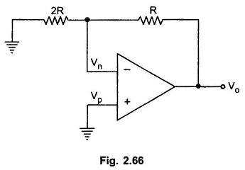
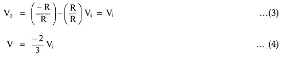
To find Vo in terms of V we concentrate on the equivalent circuit of A2, as shown in the Fig. 2.66.
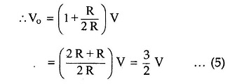
Substituting value of V in above equation we get,
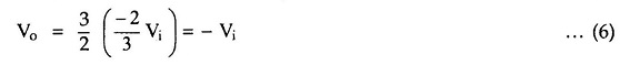
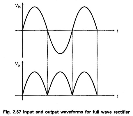
Hence for Vi < 0 the output is positive. This is illustrated in Fig. 2.67.