Impedance Diagram:
Impedance Diagram is a complex quantity having real and imaginary parts; where the real part is the resistance and the imaginary part is the reactance of the circuit.
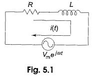
Consider the RL series circuit shown in Fig. 5.1. If we apply the real function Vm cos ωt to the circuit, the response may be Im cos ωt. Similarly, if we apply the imaginary function jVm sin ωt to the same circuit, the response is jIm sin ωt. If we apply a complex function, which is a combination of real and imaginary functions, we will get a complex response.
This complex function is Vm ejωt = Vm(cos ωt + j sin ωt).
Applying Kirchhoff s law to the circuit shown in Fig. 5.1,
we get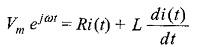
The solution of this differential equation is
![]()
By substituting i(t) in the above equation, we get
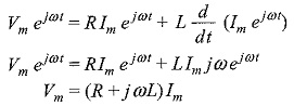
Impedance is defined as the ratio of the voltage to current function
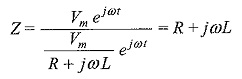
Complex impedance is the total opposition offered by the circuit elements to ac current, and can be displayed on the complex plane. The impedance is denoted by Z. Here the resistance R is the real part of the impedance, and the reactance XL is the imaginary part of the impedance. The resistance R is located on the real axis. The inductive reactance XL is located on the positive j axis. The resultant of R and XL is called the complex impedance.
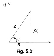
Figure 5.2 is called the impedance diagram for the RL circuit. From Fig. 5.2, the impedance Z = √R2 +(ωL)2, and angle θ = tan–1 ωL/R. Here, the impedance is the vector sum of the resistance and inductive reactance. The angle between impedance and resistance is the phase angle between the current and voltage applied to the circuit.
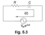
Similarly, if we consider the RC series circuit, and apply the complex function Vm ejωt to the circuit in Fig. 5.3, we get a complex response as follows.
Applying Kirchhoff’s law to the above circuit, we get
![]()
Solving this equation we get,
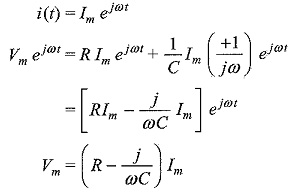
The impedance
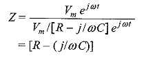
Here impedance Z consists of resistance (R), which is the real part, and capacitive reactance (XC = 1/ωC), which is the imaginary part of the impedance. The resistance,R, is located on the real axis, and the capacitive reactance XC is located on the negative j axis in the impedance diagram in Fig. 5.4.
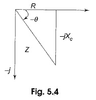
Form Fig. 5.4, impedance Z = √R2 + X2C or √R2 + (1+ωC)2 and angle θ = tan-1 (1/ωCR). Here, the impedance, Z, is the vector sum of resistance and capacitive reactance. The angle between resistance and impedance is the phase angle between the applied voltage and current in the circuit.