Filter Fundamentals in Network Analysis:
Filter Fundamentals in Network Analysis – The complete study of behavior of any filter section needs calculations of its characteristic impedance (Z0), propagation constant (γ), attenuation constant (α) and phase constant (β), using advanced mathematical calculations at any frequency. However we can easily predict pass band and stop band of a filter from an elementary consideration of variation of Z0 with frequency.
An important consideration for all Filter Fundamentals in Network Analysis is that they are constructed from purely reactive elements, otherwise the attenuation could never become zero. From the expressions of the characteristic impedances of T and π sections it is clear that, the characteristic impedance depends on the reactances Z1 and Z2 offered by purely reactive elements used in series and shunt arms of a filter. Hence the characteristic impedance Z0 varies with frequency as Z1 and Z2 both vary with frequency.
Hence in a filter, over the range of the frequencies Z0 may be either real or imaginary. Over the range of frequencies if Z0 is real, the filter and its terminating impedance will absorb power from any generator connected to it. Since filter is composed of reactive elements, it cannot itself absorb power. Hence all the power delivered by generator is passed to the load. Thus there is no attenuation i.e. α = 0. This indicates pass band.
On the other hand, if Z0 is imaginary or purely reactive, the filter and its termination cannot absorb any power. Thus, no power is passed to the load. Thus attenuation is very high, ideally attenuation is infinite. This indicates stop band.
Above discussion is also useful in determining the cut off frequency of any filter. We have already seen that in pass band Z0 is real resistive while in stop band it is purely imaginary or reactive.
Thus, we can define cut off frequency fc is the frequency at which Z0 changes from being real to being imaginary.
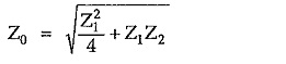
For a T section, the characteristic impedance is given by
For purely reactive T section, let Z1 = jX1 and Z2 = jX2. Substituting values of Z1 and Z2 in above formula, we can write,
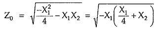
Thus, Z0 is purely imaginary if X1 and (X1/4 + X2) have the same sign. This gives stop band. We get Z0 purely resistive if X1 and (X1/4 + X2) have the opposite signs. This gives pass band.
By drawing the reactance sketches for X1 and X1/4 + X2 against frequency we can easily get cut off frequency. To get cut off frequency, the rule is as follows :
“Band of frequencies for which the curves lie on opposite side of frequency axis is pass band while the band of frequencies for which the curves lie on same side of frequency axis is stop band.” The change over point gives cut off frequency.
Constant K Sections:
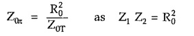
A T or π section in which series and shunt arm impedances Z1 and Z2 satisfy the relationship → Z1. Z2 = R20 where R0 is a real constant is called constant K section.
R0 is real resistance which is frequency independent. R0 is known as design impedance of the section.
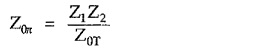
For the same series and shunt arm impedances the characteristics impedances of T and π sections can be related with each other as follows,
For a constant K section we can write,
The constant K sections either T or π, of any type of filter are known as prototype sections as other more complex sections may be derived from prototypes.