AC Fundamentals:
Let us discuss in brief, the AC Fundamentals necessary to analyse the networks consisting of various alternating current and voltage sources, resistances and inductive, capacitive reactances.
An alternating current or voltage is the one which changes periodically both in Cycle magnitude and direction. Such Change in magnitude and direction is measured in terms of cycles. Each cycle of AC Fundamentals consists of two half cycles namely positive cycle and negative cycle. Current increases in magnitude, in one particular direction, attains maximum and starts decreasing, passing through zero it increases in opposite direction and behaves similarly. The Fig. 1.14 shows a graph of alternating quantity against time.
The value of an alternating quantity at a particular instant is called its instantaneous value. Each repetition of a set of positive and negative instantaneous values of an alternating quantity is called a cycle. The time taken by an alternating quantity to complete its one cycle is known as its time period denoted as T seconds.
The number of cycles completed by an alternating quantity per second is known as its frequency. It is denoted by ‘f’ and measured in cycles/second i.e. Hertz (Hz). As the time period is the time requited to complete one cycle, we can write,
![]()
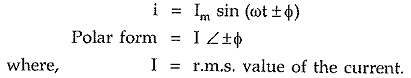
The maximum value attained by an alternating quantity during positive or negative half cycle is called its amplitude. The mathematical equation giving the instantaneous value of an alternating voltage is given by,
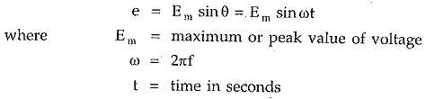
Similarly an alternating current can be expressed as,
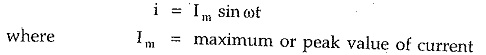
The maximum or peak value is nothing but the amplitude of an alternating quantity. In practice the alternating quantities are expressed interim of their r.m.s. values. The relation between r.m.s value and the maximum value is,
The r.m.s values are denoted by the capital letters as Vor I. Practically in AC Fundamentals analysis, most of the currents and voltages are not in phase but have some phase difference in between them.
If current lags the voltage by angle φ then its mathematical equation is,
![]()
While if current leads the voltage by angle φ then it is expressed as,
![]()
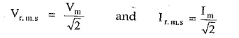
The alternating quantities are conveniently represented by the phasor diagrams. The phasor diagram is basically a polar representation of an alternating quantity. The phasors rotate in anticlockwise direction with an angular velocity ω rad/sec. All the phasors representing various alternating quantities have a particular fixed position with respect to each other. For example if there is a voltage,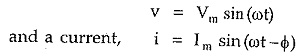
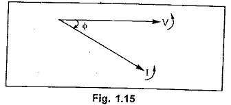
Then the corresponding phasor diagram representing this voltage and current is shown in the Fig. 1.15. In such a case we say that the current lags voltage by angle φ
Similarly consider voltage as v = Vm sin ωt and the current as,
![]()
This indicates that there is a phase difference of φ, in between them. As it is-positive, current leads voltage by an angle φ as shown in the Fig. 1.16.
Remember that while deciding lagging or leading nature of the current, the direction of rotation of phasors is always anticlockwise.
The various current and voltage phasors can be represented in polar form or rectangular form.
Consider a general equation of an alternating quantity as,
![]()
In a polar co-ordinate system, to define a particular point, it requires a magnitude and a phase angle. So given alternating voltage can be represented with a phasor of magnitude Em and an angle ± φ in a polar co-ordinate system, as shown in the Fig. 1.17.
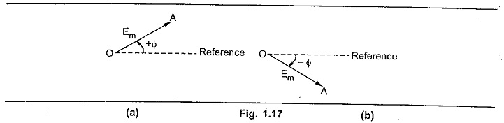
Hence in polar co-ordinate system, an alternating quantity is represented as,
![]()
Generally instead of magnitude Em the r.m.s. value of an alternating quantity is used.
Thus if φ = 0° i.e. e = Em sin ωt with its r.m.s. value as E volts then it is represented in polar form as,
![]()
This phasor lies along x-axis.
Similarly an alternating current also can be represented in the polar form.
Now consider a phasor shown in the Fig. 1.18. In polar form it is represented as E∠±φ.
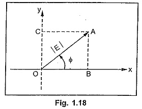
The point A can be represented in the rectangular form with x co-ordinate and y co-ordinate.
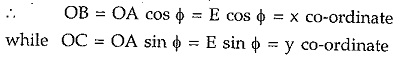
The y axis is an imaginary axis and hence in rectangular form the phasor OA is represented as, rectangular form = E cos φ + j.E sin φ
Thus if φ = 0 then the y co-ordinate of the corresponding quantity is also zero.
Thus in polar form if quantity is represented as E∠±φ then its rectangular form is E cosφ ± j E sin φ.
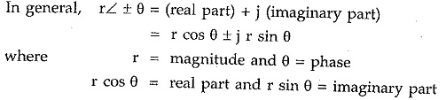
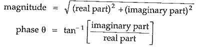
If the rectangular form is known then the magnitude and phase in polar form can be obtained as,
The conversion of a.c. quantity from polar to rectangular and rectangular to polar is very frequently required in solving AC Fundamentals problems. To have simplicity, the students can use rectangular to polar and polar to rectangular functions available in calculators.
Note : Students are advised to use the functions rectangular to polar (R—>P) and polar to rectangular (P—> R), for conversions, directly available in the scientific calculators. It must be noted that while doing any mathematical operations the magnitudes and phases of the alternating quantities must be considered. No operation should be done algebracially only on the magnitudes of the alternating quantities.
The addition and subtraction is done in rectangular form where x co-ordinates get added or subtracted and y co-ordinates are added or subtracted. The magnitudes of the quantities represented in the polar form should not be directly added or subtracted.
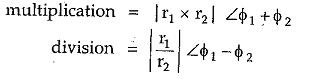
Similarly the multiplication and division is done in polar form. In multiplication, magnitudes get multiplied and angles get added while in division, magnitudes get divided and angles get subtracted.
If there are two alternating quantities as,
![]()
Then the addition or subtraction of the two is done in the rectangular form as,
![]()
While multiplication or division of the two is done in the polar form as,
The addition and subtraction of the phasors must be done in rectangular form while the multiplication and division of the phasors must be done in the polar form.
Impedance
In the alternating circuits alongwith the resistances, inductances and capacitances also play an important role. The inductances are represented by inductive reactances in AC Fundamentals circuits. An inductive reactance is the ohmic representation of an inductance denoted as XL and given by,![]()
The capacitances are represented by capacitive reactances in a.c. circuits. A capacitive reactance is the ohmic representation of a capacitance denoted as XC and given by,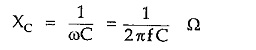
The combination of R, XL and XC present in the circuit is called an impedance of the circuit. The impedance is denoted by letter Z. But the behaviour of R, L and C is different from each other in a.c. circuits hence R, XL and XC cannot be algebraically added to find total impedance of the circuit.
Let us summarize the behaviour of R, L and C in the tabular form.
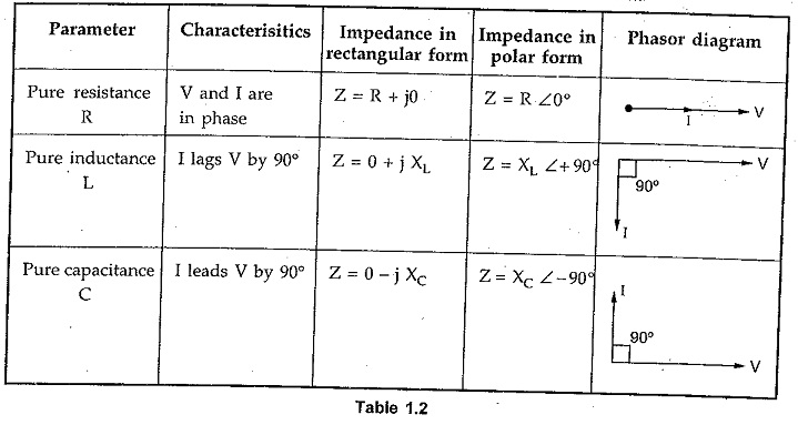
Inductive reactances are represented by positive sign + XL in the impedance while capacitive reactances are represented by negative sign – XC in the impedance.
Thus for R – L series circuit, the impedance is represented as,
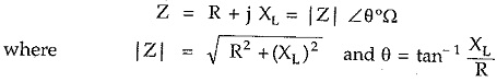
In such circuit, current lags voltage by angle θ.
For R-C series circuit, the impedance is represented as,
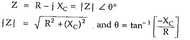
In this case θ is negative and current leads voltage by angle θ.
Power Factor
The numerical value of cosine of the phase angle between the applied voltage and the current drawn from the supply voltage gives the power factor. It is also defined as the ratio of resistance to the impedance.It is denoted as cos φ.
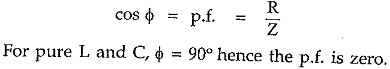
For other combinations, the p.f. is defined as lagging or leading i.e. whether the resultant current lags or leads the supply voltage.
Power
The power in AC Fundamentals circuit is given by,
Now pure inductance and capacitance does not consume any power as cos φ = 0 for such circuits. Only resistance consumes power. Hence power also can be obtained as,

Note : While calculating the equivalent impedance, it should be noted that while adding the impedances in series, the impedances must be expressed in rectangular form while multiplication and division of impedances must be carried out by expressing the impedances in the polar form
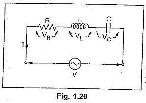
Series R-L-C Circuit
The series R-L-C circuit is shown in the Fig. 1.20.
The impedance is given by,
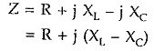
If XL > XC then resultant impedance is inductive and current I lags voltage V. If XL < XC then resultant impedance is capacitive and current I leads voltage V.
If XL = XC then circuit becomes purely resistive and I is in phase with V.
The voltage drops across the various elements are denoted as VR, VL and VC. The magnitudes of these drops are given by,
![]()
Note that algebraic sum of VR, VL and VC is not V as these three voltages are not in phase. But the vector addition of VR, VL and VC is the supply voltage V.