Inductance of Double Circuit Three Phase Line:
It is common practice to build double circuit three phase Line so as to increase transmission reliability at somewhat enhanced cost. From the point of view of power transfer from one end of the line to the other, it is desirable to build the two lines with as low an inductance/phase as possible. In order to achieve this, self GMD (Ds) should be made high and mutual GMD (Dm) should be made low. Therefore, the individual conductors of a phase should be kept as far apart as possible (for high self GMD), while the distance between phases be kept as low as permissible (for low mutual GMD).
Figure 2.15 shows the three sections of the transposition cycle of two parallel circuit three phase line with vertical spacing (it is a very commonly used configuration).
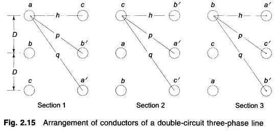
It may be noted here that conductors a and a’ in parallel compose phase a and similarly b and b’ compose phase b and c and c’ compose phase c. In order to achieve high Ds the conductors of two phases are placed diametrically opposite to each other and those of the third phase are horizontally opposite to each other. (The reader can try other configurations to verify that these will lead to low Ds.) Applying the method of GMD, the equivalent equilateral spacing is
![]()
Where
Dab = mutual GMD between phases a and b in section 1 of the transposition cycle
= (DpDp)1/4 = (Dp)1/2
Dbc = mutual GMD between phases b and c in section 1 of the transposition cycle
= (Dp)1/2
Dca = mutual GMD between phases c and a in section 1 of the transposition cycle
= (2Dh)1/2
Hence
![]()
It may be noted here that Deq remains the same in each section of the transposition cycle, as the conductors of each parallel circuit rotate cyclically, so do Dab, Dbc and Dca. The reader is advised to verify this for sections 2 and 3 of the transposition cycle in Fig. 2.15.
Self GMD in section 1 of phase a (i.e., conductors a and a’) is
![]()
Self GMD of phases b and c in section 1 are respectively
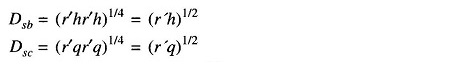
Equivalent self GMD Ds = (DsaDsbDsc)1/3
![]()
Because of the cyclic rotation of conductors of each parallel circuit over the transposition cycle, Ds also remains the same in each transposition section. The reader should verify this for sections 2 and 3 in Fig. 2.15.
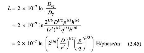
The inductance per phase is
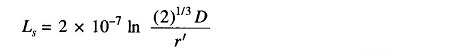
The self inductance of each circuit is given by
Equation (2.45) can now be written as
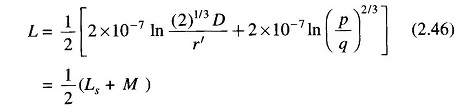
where M is the mutual inductance between the two circuits, i.e.
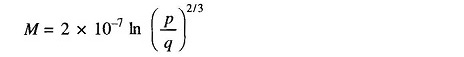
This is a well known result for the two coupled circuits connected in parallel (at similar polarity ends).
If
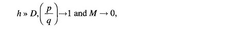
i.e. the mutual impedance between the circuits becomes zero. Under this condition
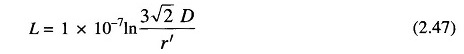
The GMD method, though applied above to a particular configuration of a double circuit three phase Line, is valid for any configuration as long as the circuits are electrically parallel.
While the GMD method is valid for fully transposed lines, it is commonly applied for untransposed lines and is quite accurate for practical purposes.