Attenuation and Distortion of Travelling Waves:
As a Travelling Waves moves along a line, it suffers both attenuation and distortion. The decrease in the magnitude of the wave as it propagates along the line is called attenuation. The elongation or change of wave shape that occurs is called distortion. Sometimes, the steepness of the wave is reduced by distortion. Also, the current and voltage wave shapes become dissimilar even though they may be the same initially. Attenuation is caused due to the energy loss in the line and Distortion of Travelling Waves is caused due to the inductance and capacitance of the line. The energy loss may be in the conductor resistance as modified by the skin effect, changes in ground resistance, leakage resistance and non-uniform ground resistances etc.
The changes in the inductance are due to the skin effect, the proximity effect and non-uniform distribution effect of currents, and the nearness to steel structures such as transmission towers. The variation in capacitance is due to capacitance change in the insulation nearest to the ground structures etc. If the wave shapes remain approximately the same, then the surge impedance can be taken to be constant, in which case the attenuation can be estimated. The other factor that contributes for the attenuation and distortion is the corona on the lines. For distortionless lines, the attenuation is approximated as a loss function φ(V), considering that the attenuation is due to the energy lost per unit length of the line in the resistance as the wave travels. It can be shown that
![]()
For different line conditions, φ(V) and attenuation are as follows:
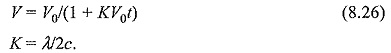
(i) For lines having all the parameters R, L, G and C
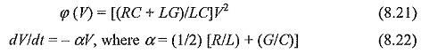
From Eq. (8.20), α is called the attenuation factor.
![]()
where the initial voltage at t = 0 is taken as V0.
(ii) The Skilling formula
If φ(V) is assumed to be equal to β (V – VC), where VC is critical corona voltage; then
![]()
and if the initial voltage at t = 0 is taken as V0, then
![]()
(iii) The quadratic formula
If φ(V) is assumed to vary as
![]()
Integrating the above equation, we get
![]()
(iv) The Foust and Manger formula
Here, φ(V) is assumed to be equal to λV3, so that
![]()
It follows from the above equation that
The Foust and Manger formula is simpler for the purpose of calculation and the exceptional attenuation obtained in Eq. (8.21) can be used easily for all mathematical operations.
Attenuation due to Corona:
The effect of corona is to reduce the crest of the voltage wave under propagation, limiting the peak value to the critical corona voltage. Hence, the excess voltage above the critical voltage will cause power loss by ionising the surrounding air. This mechanism is explained as follows: the Travelling Waves is divided into a number of sections corresponding to different voltage levels, each voltage level corresponding to a different velocity of propagation since each lamination ionises a different diameter of the air layer surrounding the conductor and hence have different capacitances. Hence, ‘a Distortion of Travelling Waves is caused in the wave shape. This explanation ignores the power loss due to corona. The mechanism of corona power loss as explained by Skilling is as follows:
The charges liberated by the ionisation of air surrounding the conductor takes such positions on the conductor so as to make the critical field intensity (gradient) for air to reach values that cannot be exceeded. The supply of space charge to the above regions continue as long as the voltage is increasing and the energy is supplied. After the crest of wave is reached and the wave is trailing, the space charge remains constant in magnitude. The only energy loss caused during this period is due to the diffusion of ions, a process which is very slow. Based on this explanation Skilling gives the formula for corona power loss as P = K(V — Vc)2 , where Vc is the critical corona voltage and K is a constant.