Characteristics of Data Transmission Circuits:
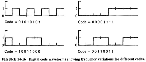
Bandwidth Requirements – Characteristics of Data Transmission Circuits is the most instances consists of pulse-type energy. The data stream is similar to a square-wave signal with rapid transitions from one voltage level to another, with the repetition rate depending on the binary representation of the data word. For instance, if an 8-bit word has the value 01010101, the resulting voltage graph would appear as a series of four square waves with each negative half-cycle equal to each positive half-cycle. If, however, the data word has the form 00001111, the voltage graph would appear as a single square wave with negative and positive half-cycles equal but longer than the first example. Figure 14-16 shows the voltage graphs for these and other binary words. It can be seen that data circuits must provide a bandwidth for the data transmissions they carry. This will be governed by the pulse rate variations just explained, and by the fact, indicated in earlier, that even a single square wave occupies a frequency range because of the harmonics present.
Since many data transmissions utilize telephone channels, the bandwidth of the telephone is an appropriate consideration. The internationally accepted standard telephone channel occupies the frequency range of 300 to 3400 Hz, this referred to within the industry as a 4-kHz channel. In certain difficult or expensive applications, such as HF radio or some submarine cables, 3-kHz circuits, in which the frequency range is 300 to 2800 Hz, are used. Neither channel will encompass all the audible spectrum, but each will cover the range into which speech falls and convey enough of the components of speech to ensure intelligibility and voice recognition. The signals which fall outside the, channel bandwidth are attenuated by filters so that they will not interfere with other signals.
When data is sent over telephone channels, the speed must be limited to ensure that the bandwidth required by the Characteristics of Data Transmission Circuits will not exceed the telephone channel bandwidth. The faster the data is transmitted, the greater the bandwidth will need to be to accommodate it.
Data Transmission Speeds – The rate of data transfer depends on several aspects of the transmission channel, of which signaling speed is very important. Transmission engineers often refer to the transmission speed of a communications channel as the channel’s baud rate. The baud is an important unit of signaling speed. In a system in which all pulses have equal duration, the speed in bauds is equal to the maximum rate at which signal pulses are transmitted. This should be recognized as different from information bit rate. In a system which uses only one information bit per signaling pulse, i.e., a binary system, the baud rate and the bit rate happen to be the same. In systems which encode the data in such a way that more than one information bit can be placed on each signaling pulse, the information bit rate will exceed the baud rate.
To relate baud rate to bandwidth, the observations of the twentieth-century electrical engineer Nyquist are used. Nyquist determined that one cycle of a Characteristics of Data Transmission Circuits can contain a maximum of two bands. The result is that the maximum signaling speed in bauds is equal to twice the bandwidth of the channel. This is theoretical and could be achieved only in an ideal channel which had no noise or distortion.
As indicated above, the baud is a unit of signaling speed, but information transfer can occur at a rate equal to or different from the baud rate. Multilevel and encoded data elements can be used to provide information transfer rates at speeds greater than the baud rate. In the Bell system 201A and 201B data sets, for example, data streams are converted to 2-bit pairs. Each 2-bit pair can have only one of four values, 00, 01, 10 or 11. Each of the 2-bit pairs is converted to a phase value in the data set, 00 being represented by 90 degrees, 01 by 180 degrees, 10 by 270 degrees, and 11 by 0 degrees. Each of the 2-bit elements is called a dibit. This is, therefore, a four-level code. Dibit-encoded data can be transmitted by using half the number of bands required for the nonencoded data.
Multilevel encoding is used to increase information transfer, but it has drawbacks. It compromises the ability to detect code values reliably, since there are multiple values for each signaling element, which previously had only two: ot•I or OFF. Even with this limitation, given a relatively noiseless and distortion-less transmission channel, multilevel coding can provide valuable transmission-efficiency improvements.
We already know the maximum capacity for a noisy channel with a given noise level. This formula provides the ideal expectations, which are not realizable in practice. Nonetheless, the Shannon-Hartley law does set the upper limit for a channel and encourages continued coding improvements to increase channel capacity.
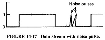
Noise – The Shannon-Hartley law is related to random noise, but impulse noise can also be harmful to signals. The sampling theorem shows that all values of a signal can be determined by sampling the signal at a rate equal to at least twice the bandwidth. Noise affects this sampling process because the noise pulse will be interpreted as a data bit ( see Figure 14-17), if the noise impulse occurs at the time a sample is taken, and has an amplitude equal to or exceeding the minimum level recognized by the system as a mark. The potential for impulse noise to become a source of errors increases with the number of levels of each code element. To achieve the 30,880-bps rate mentioned in the above example, it may be shown that five levels would be required for each code element. A noise-free channel would be necessary to preclude noise-induced data errors, but noise-free channels do not exist in practice. It is noise, among other impairments, which tends to limit the actual 4-kHz channel data speeds to 10,800 bps or less.
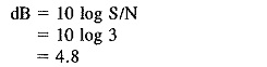
The effect of noise on the data channel can be reduced by increasing the signal-to-noise ratio. For an ideal 3-kHz channel, the Nyquist rate (twice the bandwidth, as discussed) would be 6000 bps. A binary system using this channel would require a minimum signal-to-noise ratio of 3:1, or 4.8 dB. This is calculated by using Equation (14-1), as follow’s:
![]()
where
S/N = Signal-to-noise ratio
NR = Nyquist rate
δf = Channel bandwidth
For the ideal 3-kHz channel:
![]()
To obtain the decibel value:
It can be shown that a system using a three-level code must have a signal-to-noise ratio of 8.5 dB, or 3.7 dB greater, for equal performance in the same channel. A four-level code requires a signal-to-noise performance of 11.7 dB. Improvement in the signal-to-noise ratio makes use of multilevel encoding feasible.
Crosstalk – Any transmission system which conveys more than one signal simultaneously can experience crosstalk, which is interference due to the reception of portions of a signal from one channel in another channel. This is common in multiplexed systems in which inadequate procedures are employed to ensure that over-modulation of the various carriers of the multiplexed groups is prevented. In modem transmission systems which convey many channels of voice and data simultaneously, the systems will become “loaded,” or heavily utilized, so that the control of levels of the individual channels and the group levels becomes very important in order to preclude crosstalk. Data transmission engineers have developed specific level-setting parameters to ensure that as the circuit loading increases, crosstalk will not become a problem.
Crosstalk interference can also occur through electromagnetic interaction between adjacent wires. If the wires of two signal-carrying circuits run parallel with each other, it is possible for the signal from one circuit to be induced by electromagnetic radiation into the second circuit. This phenomenon becomes more pronounced when the length of parallel circuits is extensive. This type of crosstalk is reduced by using twisted pair cables and balanced circuits along with shielding.
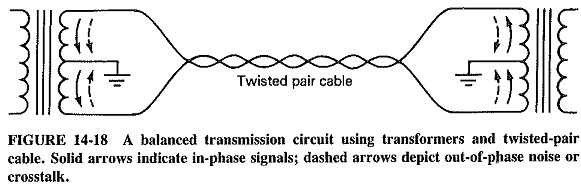
In a balanced circuit, a transformer is placed at each end of the circuit. The transformers are carefully constructed to provide a center tap which is at the exact electrical center of the winding which connects to the transmission circuit. The center taps at each end are grounded. As shown in Figure 14-18, if twisted pair cables are used for the transmission circuit, noise or signals from other circuits will be induced into both wires at equal levels. When the crosstalk or noise reaches the transformer, it enters as out-of-phase signals from the two wires and cancels out in the transformer windings. The circuit signal, however, enters the transformer in phase. Each side of the transformer forms a circuit with ground and the signal transfers through the transformer intact. The crosstalk and noise are reduced, but the signal is unaffected.
Another way to reduce crosstalk is to use shielded cables. If the twisted pairs are placed inside a braided or metal foil shield, the induction between pairs take place as easily. The shields are grounded to drain off the induced signals and noise.
Echo suppressors – As discussed already, echo suppressors or echo cancellers are used on long-distance circuits, in an effort to overcome echoes caused by circuit imbalances. This is of significance to Characteristics of Data Transmission Circuits because a lot of it occurs over the public switched telephone network, nationally and internationally.
Although the use of echo suppressors improves voice communications, it is incompatible with Characteristics of Data Transmission Circuits. Because a lot of data transmissions are bothway, or quickly alternating from one direction to the other, they require the capability of bidirectional transmission at standard levels, or at least rapid response and interrupt capability. For this type of operation to be accomplished, it is necessary to disable the echo suppressor. In fact, so-called “tone-disablable” echo suppressors have been designed to accommodate the needs of data users. If a 2025-Hz tone is applied to the line for approximately 300 ms prior to the start of transmission, such an echo suppressor will be disabled and bidirectional communication can proceed. If a gap in the transmission greater than 100 ms occurs, the echo suppressor will be reactivated.
Distortion – Communication channels tend to react to signals of different speeds within their bandpass in different ways. Specifically, signals of different frequencies can be passed by the channel with different values of amplitude attenuation and at different propagation speeds. The result is distortion.
Of great importance to systems using phase modulation is phase delay (or envelope delay) distortion. Phase delay distortion occurs in a channel when signals of one frequency are passed through the circuit at a different speed than other signals. The resulting distortion can take the form of intersymbol interference. Since characters which have lower-frequency components pass at a different speed than data characters with high-frequency components, it is possible in higher-speed circuits for portions of one character to enter or remain in the time slot allocated to other characters.
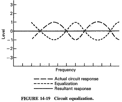
Equalizers – Phase delay distortion can be reduced to acceptable levels by using equalization on the channel. As shown in Figure 14-19, it is possible to plot the delay characteristics of the channel and insert an equalizer which can be adjusted to compensate for the delay abnormalities. The result is a channel relatively free of phase delay.
Equalizers can be obtained which are automatic in nature. These equalizers precede data transmission with a short “training period” during which test pulses are used to determine the delay characteristics of the channel. The equalizer automatically varies its delay characteristics while sampling the return signal to determine when the channel delay plus equalizer delay reach proper tolerances. At that time, data transmission commences. The Characteristics of Data Transmission Circuits is thereafter sampled during transmission to ensure that equalization settings are appropriate, with modifications made as required. This type of equalization is called Adaptive Equalization.
Preset equalization or conditioning follows the same processes as adaptive equalization except that the equalization is set prior to transmission and then updated only during breaks in transmission, using special test sequences. This is not as flexible as adaptive equalization, since the transmission must be interrupted to permit transmission of test data sequences whenever the channel characteristics alter. However, it is quite acceptable for dedicated circuits with fixed terminations. It is possible to lease national or international circuits that have been conditioned to domestic or international standards. Understandably, though, such circuits are more expensive than unequalized circuits.