Feedback Pair Connection – Operation and its Equivalent Circuit
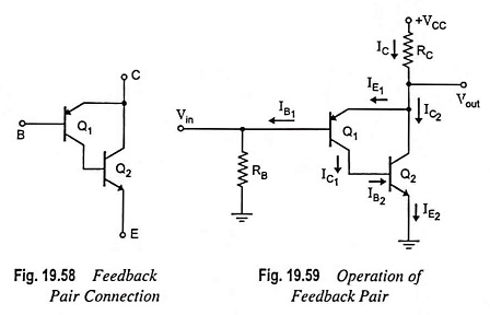
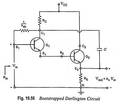
Feedback Pair Connection - Operation and its Equivalent Circuit: The feedback pair connection (Fig. 19.58) is a two-transistor circuit that operates like the Darlington amplifier. It makes use of a PNP transistor driving an NPN…
Comments Off on Feedback Pair Connection – Operation and its Equivalent Circuit
November 25, 2022