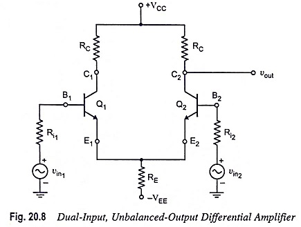
Dual Input Unbalanced Output Differential Amplifier
Dual Input Unbalanced Output Differential Amplifier: It is an important configuration and converts dual inputs into a single ended output. In this configuration, two input signals are applied and the output is measured at only…
Comments Off on Dual Input Unbalanced Output Differential Amplifier
November 26, 2022