Starting of Induction Motor Drives:
Starting of Induction Motor Drives arrangement is chosen based on the load requirements and nature of supply (weak or stiff). It may be required to have following features:
- Motor should develop enough starting torque to overcome friction, load torque and inertia of motor-load system, and thus, complete the starting process within a prescribed time limit.
- Starting current magnitude should be such that it does not cause the overheating of the machine and does not cause a dip in the source voltage beyond a permissible value.
Usually, a motor draws 5 to 7 times rated current during starting. When load torque during starting and motor-load-inertia are not large, the Starting of Induction Motor Drives process is over in a few seconds and therefore, motor temperature does not exceed the permissible value. In such applications, motor can always be started direct on line, provided the voltage dip caused by large starting current is not beyond a permissible value. For small size motors voltage dip in the supply line is usually below acceptable level. When the motor is of large capacity and/or fed from a weak system, some starting arrangement becomes necessary for reducing the starting current. In these applications it does not matter if the reduction in starting current is accompanied by a reduction in starting torque.
When either the load torque during starting is high or load inertia is large, the Starting of Induction Motor Drives process takes long time. If motor carries large current during starting, it will get damaged due to overheating. Therefore, motor cannot be started direct on line. In these cases, those methods of starting which allow a decrease in starting current without a decrease in starting torque are employed. In some applications an increase in starting torque accompanied by a decrease in starting current may be required.
In a squirrel-cage motor some measures for improvement of starting performance may. be taken at design stage, as in case of high slip, deep-bar and double cage squirrel-cage motors. When needed, methods employed for starting squirrel-cage motors are:
- Star-delta starter
- Auto-transformer starter
- Reactor starter
- Saturable reactor starter
- Part winding starter
- AC voltage controller starter
- Rotor resistance starter is used for starting of wound-rotor motor:
Methods (1)-(5) and (7) are described here and Method (6) in Sec. 6.11.
Star-Delta Starter:
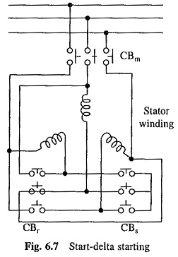
In this method, an induction motor designed to operate normally with delta connection is connected in star during starting. This allows reduction in stator voltage and current by 1/√3. Since motor torque is proportional to the square of stator terminal voltage, starting torque is reduced to one-third. A circuit for star-delta starting is shown in Fig. 6.7. Circuit breakers CBm and CDs are closed to start the machine with star connection. When steady-state speed is reached CBs is opened and CBr is closed to connect machine in delta.
Auto-transformer Starter:
Reduced voltage for starting can also be obtained from an auto-transformer. For a secondary to primary turns ratio of aT, motor terminal voltage and stator current are reduced by aT. This reduces the current drawn from supply by a2T. Since torque is proportional to the square of motor terminal voltage, it is also reduced by a2T. After the motor has accelerated, it is connected to full supply voltage. An auto-transformer starter circuit is shown in Fig. 6.8(a). First, CBs1 is closed followed by CBs2. When motor has accelerated to full speed, CBs2 is opened and CBm closed. Now CBs1 is opened to disconnect auto-transformer from the supply.
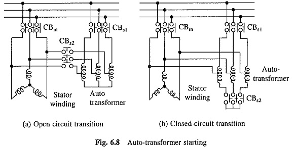
Closed Circuit Transition:
In both, star-delta and auto-transformer starting methods, changeover from low voltage to full voltage connection disrupts the flow of stator current and stator field collapses. Rotor current continues to flow due to its large time constant. Field produced by rotor currents induces voltages in the stator windings. Phase of the induced voltages is independent of supply voltages. A large current inrush is produced at the time of re-connection when induced and supply voltages are out of phase. When the current inrush is not acceptable, closed circuit transition is employed. A closed-circuit transition scheme for an auto-transformer starter is shown in Fig. 6.8(b). It employs three circuit breakers: CBs1, CBs2 and CBm. First CBs2 is closed to close the star point connection of the auto-transformer. CBs1 is closed next. This completes low voltage connection of auto-transformer and the motor starts. After steady-state speed is reached, circuit breaker CBs2 is opened. Motor now runs with the upper part of auto-transformer phase windings in series with the stator. Windings simply function as series reactors. Now circuit breaker CBm is closed, which bypasses series reactors and connects motor directly to the supply.
At the beginning of starting alternatively, first CBs1 is closed instead of CBs2. Then motor and transformer will not produce magnetizing current surge simultaneously.
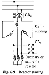
Reactor Starter:
Starting current can also be reduced by connecting a three-phase reactor in series with stator.
When motor reaches full speed, the reactor is bypassed. Figure 6.9 shown such a scheme. CBm is closed to start the machine. After full speed is reached CBs is closed to short the reactor. It is advantageous to connect reactor at the neutral end of stator winding. This minimizes its voltage rating and also maintains its voltage and the voltage of breaker CBs at neutral potential during normal motor operation.
Soft Start Using Saturable Reactor:
In some applications starting torque must be controlled steplessly. For example in textile machines, it must be varied smoothly, otherwise fibre threads will break during starting. Such a starting arrangement is termed Soft Start.
Thyristor voltage controller scheme is now widely used for soft start. A number of existing drives also employ saturable reactor starter in which a three-phase saturable reactor is connected in series with the stator. Saturable reactor has dc control winding. Reactance of saturable reactor can be varied steplessly by changing the control winding current. For starting, reactance is initially set at the highest value. Starting torque is close to zero. Reactance is now reduced smoothly by increasing the control winding current. This gives stepless variation of starting torque. Consequently, motor starts without any jerk and accelerates smoothly.
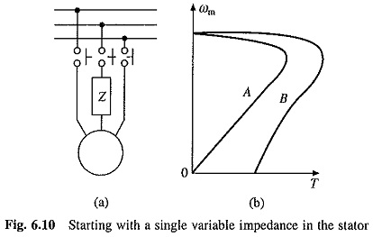
Unbalanced Starting Scheme for Soft Start:
For soft start, a cheaper alternative shown in Fig. 6.10(a), can also be employed. It consists of a variable impedance Z in one of the phases of machine. When impedance is very high, machine operates with single phasing and its speed-torque characteristic is similar to characteristic A of Fig. 6.10(b), with a zero starting torque. When impedance is completely removed, speed torque curve is similar to the characteristic B, which is the natural characteristic of machine. For intermediate values of impedance, speed-torque curve will lie in between curves A and B. A smooth start, without a jerk, is achieved when impedance is controlled steplessly. The impedance may be a variable resistor or a single phase saturable reactor.
Motor operates with unbalanced stator voltages, therefore, copper losses increase. Thus, this scheme is suitable only for short duty operation.
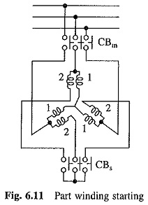
Part Winding Starting:
Some squirrel-cage motors have two or more stator windings which are connected in parallel during normal operation. During starting, only one winding is connected. This increase stator impedance and reduces starting current. Such a starting scheme is called Part Winding Starting. Its implementation for a machine with two stator windings is shown in Fig. 6.11. Machine starts with winding 1 when CBm is closed. After full speed is reached, CBs is closed to connect winding 2.
Rotor Resistance Starter:
Wound-rotor motors are generally started by connecting external resistors in the rotor circuit (Fig. 6.12(a)). The highest value of resistance is chosen to limit current at zero speed within the safe value. As the motor accelerates, sections in the external resistor are cut out one-by-one by closing contacts C1, C2 and C3 so as to limit the rotor current between specified maximum and minimum values (Fig. 6.12(b)).
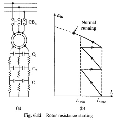
Since most of the rotor copper loss occurs in external resistors, rotor temperature rise during starting is substantially lower compared to starting methods described earlier. Important feature of this Starting of Induction Motor Drives method is that the starting torque and torque-to-current ratio are high. It is, therefore, suitable for applications requiring fast acceleration, frequent starts and stops, starting with heavy load, and starting with high inertia load.
While maximum torque is independent of rotor resistance value (Eq. (6.13)), speed at which maximum torque is produced can be controlled by changing the value of external resistors (Eq. (6.12)). External resistors can therefore be varied to accelerate the machine at maximum torque.