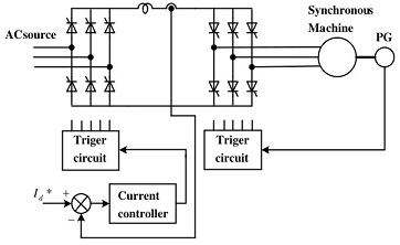
Synchronous Motor Drives:
Variable frequency drives employing synchronous motor are receiving considerable interest, and are even becoming competitors to both induction motors and dc motors. These are popular as drives for very high power applications, such as pumps, fans, conveyors, etc. The stator of the synchronous motor is supplied from a thyristor power converter capable of providing a variable frequency supply. The rotor, depending upon the situation, may be constructed with slip rings, where it conforms to a conventional rotor. It is supplied with dc through slip rings. Sometimes rotor may also be free from sliding contacts (slip rings), in which case the rotor is fed from a rectifier rotating with rotor.
An induction motor operates at lagging poWer factor and hence the converter supplying the same must invariably be a force commutated one. A synchronous motor, on the other hand, can be operated at any power factor by controlling the field current. For operation at unity power factor and lagging power factors the inverter must be force commutated. However if the power factor is near unity the inverter size is reduced, besides reducing armature copper loss. For operation at leading power factors the motor must be overexcited. The motor is in a position to supply the reactive power required by the inverter. In other words, the machine voltages can be used for commutation. The inverter in this case is load commutated. The load commutation is possible with cycloconverters and current source inverters but not with voltage.
A machine is said to be self controlled if it gets its variable frequency from an inverter whose thyristors are fired in a sequence, using the information of rotor position or stator voltages. In the former, a rotor position sensor is employed, which measures the rotor position with respect to the stator and sends pulses to the thyristors. Thus the frequency of the inverter output is decided by the rotor speed. This kind of control makes it possible to control the angle between the stator and rotor mmf or load angle. The machine behaviour is decided by the torque angle, and voltage/current. Such a machine can be looked upon as a dc motor having its commutator replaced by a converter connected to stator. The rotor may be a conventional one supplied by dc power through slip rings, or it may be of special construction to avoid sliding contacts. In this case it is fed from a rectifier rotating with the rotor. The self controlled motor has properties of a de motor both under steady-state and dynamic conditions and therefore is called commutator less motor (CLM). These machines have better stability behaviour:, They do not fall out of step and do not have oscillatory behaviour, as in normal synchronous motors.
Alternatively, firing signals can be derived from the phase position of stator voltages in which case the mechanical rotor position sensor can be dispensed with. The synchronous machine with the inverter can be considered to be similar to a line commutated converter where the firing signals are synchronised with the line voltage. In this case the firing pulses of the inverter are synchronised with the machine voltages. The natural commutation using machine voltages takes place. Thus the machine voltages are used for both control as well as commutation. The frequency of the inverter is the same as that of the voltages.
The dynamic behaviour of the motor depends upon the type of control used. The machine however retains the properties of a dc motor in both the types of control.
An overexcited synchronous motor will be able to provide the necessary reactive power required for commutation of thyristors. The inverter commutation circuit has a very simple configuration as the capacitors, diodes and auxiliary thyristors are absent. The converter is economical with better utilisation of the thyristors. However, the machine commutation has a disadvantage. At very low speeds (up to about 10% of base speed) the machine voltages are insufficient to provide satisfactory commutation. Special methods are required to run the motor at these speeds, beyond which machine commutation can be used. Commutation assistance is required only at low frequencies and hence the commutation circuit required will be relatively simple and cheap. Artificial commutation of conducting thyristors is possible by means of a controlled thyristor across the link inductance. The motor is underutilised as it is operating at leading power factor.
A self controlled synchronous motor is, therefore, a, substitute for a dc motor drive and finds application where a dc motor is objectionable due to its mechanical commutator, which limits the speed range and power output.
