Sensors Based Computer Data Systems:
This Sensors Based Computer Data Systems describes hardware/software which is commercially available at several levels of completeness, ranging from single board computer “front ends” to stand alone system and high level programming languages.
Even the simplest and least expensive devices require considerable electronics/computer expertise on the part of the user, access to a micro-computer development system and sufficient engineering time to integrate the interface and computer into a working overall system. Since micro-computer system design is specialised and beyond the range of this text, we give only a brief description of micro-computer interface boards, shown in Fig. 17.27 as an example. These are available from several manufacturers, and interfaced with most popular micro-computers.
To reduce program storage requirements and execution times (at the expense of memory address area), a memory mapped I/O is often employed. Note that analog inputs (up to 32 single ended inputs 16 differential inputs) are processed through a multiplexer, programmable gain amplifier (PGA), sample/hold (S/H), and A/D converter in a fashion very similar to that of a data logger.
However, since we wish to handle HF signals, a successive approximations (rather than dual-slope) A/D converter (maximum throughput rate 28 kHz) and an electronic (rather than reed switch) multiplexer are necessary.
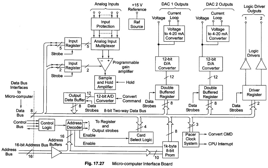
It is possible to obtain two (optional) D/A converters for driving analog recorders, generating analog control signals, etc. The hardware problems are reduced to a minimum by the use of such an interface card. Also, the overall system throughput rate must be less (often much less) than the 28 kHz value given above, since software execution time must be added to the A/D conversion time.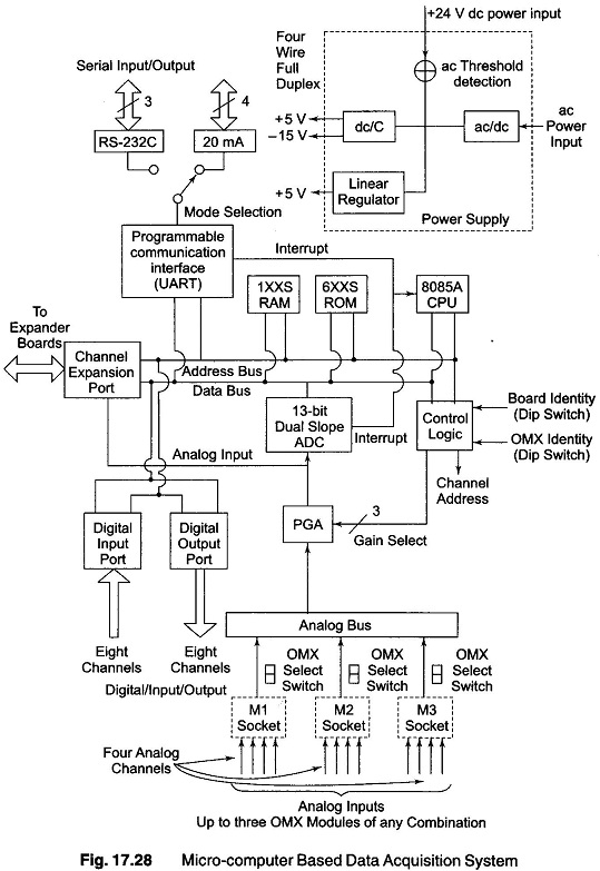
Figure 17.28 shows a single board, micro-computer based data acquisition system designed to accept multichannel analog and digital inputs and provide digital output to a host computer (usually a mini-frame or Main frame supporting high level languages such as BASIC and FORTRAN) through a standard serial communications port (RS 232C or 20 mA current loop). The on-board micro-computer unburdens the host computer by allowing supervisory control.
It performs data acquisition control, linearlization, conversion to engineering units, limits checking, interface control, and data output formatting. The analog channels are scanned continuously (15 to 30 channels per second) and the resultant data are stored in the micro-computer memory (RAM). The data in the RAM is refreshed on a continuous basis (the latest data is kept in memory), so that requests for data from the host are serviced immediately. Upon receipt of a transit command, the micro-computer [via. the UART (Universal Asynchronous Receiver Transmitter)] begins transmitting a string of data in the ASCII format to the host. No programming of the micro-computer is necessary, since it is preprogrammed by the firmware to respond to host commands.
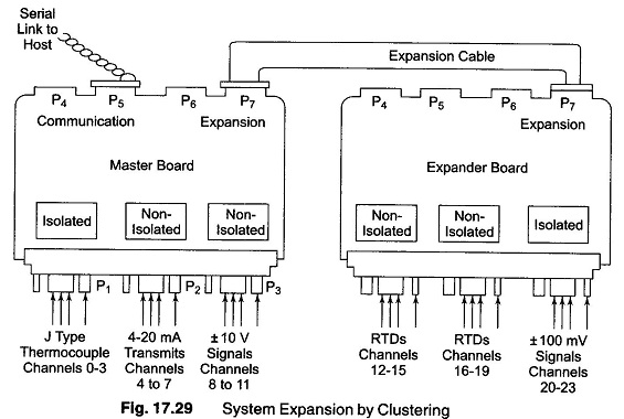
The 12 channels of the analog input are broken into 3 groups of 4, and convenient 4 channel plug-in modules for thermocouples, RTDs, strain gauge transducers, etc. are available. Up to three expander boards can be controlled by a master board, creating a cluster as shown in Fig. 17.29. Up to 8 clusters can be operated from the same host, providing expansion to 384 channels.
For those applications in which a sensor based measurement and control system with comprehensive and easy to use computer processing is designed, with a minimum of user engineering effort, complete stand alone systems such as that of Fig. 17.30 are available.
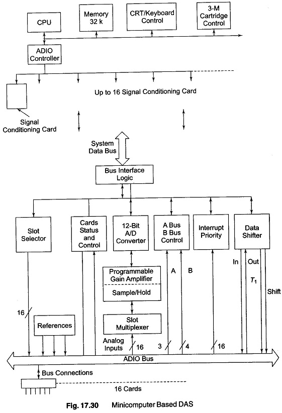
Analog and digital input/output is through a plug-in signal conditioning cards, space for 16 cards is provided (expandable up to 256 cards). A wide selection of cards functions are available, allowing easy interfacing with all kinds of sensors and control devices. Single cards are often themselves multichannel devices with a multiplexer on the card. Thus, two level of computer controlled multiplexing are present, slot multiplexing (chooses the card slot desired) and card channel multiplexing (selects the channel wanted on the chosen card).
For example, a single digital input card provides 16 channels (bits) while the analog input card has 32 channels (single ended) or 16 channels (differential). This analog card has its own PGA (gain = 1, 16, 256) which combined with the PGA of the central controller (gain = 1, 2, 4, 8), allows versatile selection of channel gain under program control. Thermocouple cards are four channel units, which share a common reference-junction compensation circuit and have fixed gain. Lineraization is accomplished in software by a general purpose polynomial sub-routine. A fast (25 ,μS conversion time) successive approximation A/D converter allows rapid scanning and storage of analog input (mixed channels at 2 kHz, single channel at 4 kHz). A mini computer specially designed for measurement control applications has 32,000 words of 16 bit MOS random access memory (RAM) augmented by 105 k bytes of cartridge tape mass storage.
Programming is a Macbasic (a version of BASIC) specially enhanced for easy system operation. For example, the statement![]()
assigns to the variable V, the value of the analog voltage on channel 1 of the analog input card in the I/O slot 2, minus 1.53. Similarly, the statement![]()
places a voltage of 4.44 V on Channel 3 of the analog output card in I/O slot 1. For digital input variable DIN
![]()
takes the digital logic level from Channel 1 of the digital input card in I/O slot 3 and places it in I′, where I′ is an integer variable.
For digital output variable DOT![]()
turns on Channel 3 of the digital output card in I/O slot 8 if X = 1 and turns it off if X = 0.
System timing functions are eased by the availability of statements such as
![]()
which causes the program to wait 5.6 before proceeding to the next statement.
A common requirement of many applications is the ability to perform several operations or tasks independently of one another in the same program. Examples include the monitoring of several analog signals in the laboratory or control of several process loops. To provide for this requirement, Macbasic is structured as a multitasking language and contains the necessary words for implementation.
Tasks are groups of Macbasic language statements that are defined as a task, and are executed each time the task is activated unconditionally or by satisfaction of a condition (such as an external event), or on a periodic basis. Up to 18 tasks may be defined at a given time and if more than one task is active at a given moment, the active task share resources and run simultaneously, unless priority is assigned to a particular task. If a task completes its operation, it can DISMISS itself an d return its resources to the system until the task is reactivated.