Resistive Position Transducer:
The principle of the Resistive Position Transducer is that the physical variable under measurement causes a resistance change in the sensing element. (A common requirement in industrial measurement and control work is to be able to sense the position of an object, or the distance it has moved).
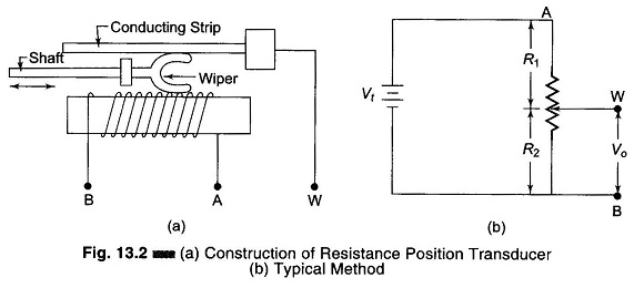
One type of displacement transducer uses a resistive element with a sliding contact or wiper linked to the object being monitored or measured. Thus the resistance between the slider and one end of the resistance element depends on the position of the object. Figure 13.2(a) gives the Construction of Resistance Position Transducer.
Figure 13.2(b) shows a typical method of use of resistive position transducer. The output voltage depends on the wiper position and is therefore a function of the shaft position. This voltage may be applied to a voltmeter calibrated in cms for visual display.
(Typical commercial units provide a choice of maximum shaft strokes, from an inch or less to 5 ft or more.) Deviation from linearity of the resistance versus distance specifications can be as low as 0.1 – 1.0%.
Considering Fig. 13.2(b), if the circuit is unloaded, the output voltage Vo is a certain fraction of Vt, depending upon the position of the wiper.
Therefore,

When applied to resistive position sensors, this equation shows that output voltage is proportional to R2, i.e. the position of the wiper of the potentiometer. If the resistance of the transducer is distributed uniformly along the length of travel of the wiper, the resistance is perfectly linear.