Non Inverting Amplifier Theory:
Direct-Coupled Noninverting Amplifier – The Non Inverting Amplifier Theory circuit in Fig. 14-14 behaves similarly to a voltage follower circuit with one major difference. Instead of all of the output voltage being fed directly back to the inverting input terminal (as in a voltage follower), only a portion of Vo is fed back. The output voltage is divided by resistors R2 and R3, and the voltage across R3 is applied to the inverting input terminal. As in the case of the voltage follower, the output voltage changes as necessary to keep the inverting input terminal voltage equal to that at the noninverting input. Thus, the voltage VR3 always equals Vi, and the output voltage is then determined by the resistances of R2 and R3.
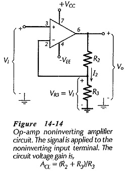
Because the signal voltage is applied to the op-amp noninverting input terminal, the output always has the same polarity as the input. A positive-going input produces a positive-going output, and vice versa. Thus, the input is not inverted (at the output), and the circuit is identified as a noninverting amplifier.
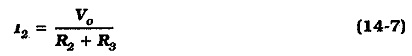
The voltage divider current (I2) is always selected to be very much larger than the operational amplifier input bias current, and
![]()
Also, in Fig. 14-14 it is seen that
The circuit voltage gain is,
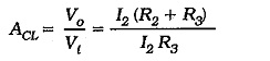
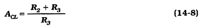
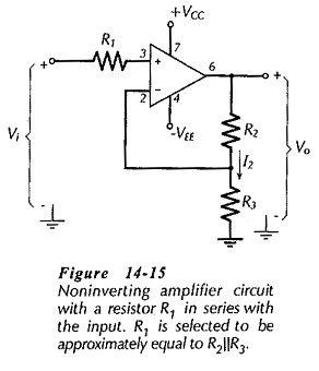
Figure 14-15 shows a Non Inverting Amplifier Theory with a resistor (R1) connected in series with the noninverting input terminal. As in the case of other op-amp circuits, this is done to equalize the resistor voltage drops produced by input bias current. In this case, R1 is selected to be approximately equal to the resistance ‘seen looking out of’ the inverting input terminal. Thus,
![]()
The input and output impedances for a Non Inverting Amplifier Theory are easily determined from the negative feedback equations.
Design of a noninverting amplifier mostly involves determining suitable voltage divider resistors (R2 and R3).
Capacitor-Coupled Noninverting Amplifier:
When a noninverting amplifier is to have a signal capacitor-coupled to its input, the op-amp noninverting input terminal must be grounded via a resistor to provide a path for the input bias current. This is illustrated in Fig. 14-16, where R1 allows for the passage of IB1. As in the case of the capacitor-coupled voltage follower, the input resistance is essentially equal to R1 for the capacitor-coupled Non Inverting Amplifier Theory.
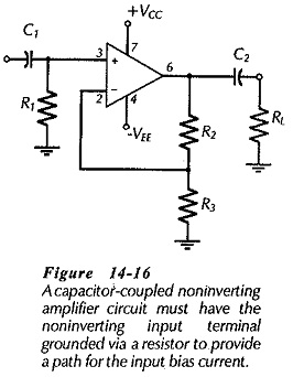
Resistors R1, R2 and R3 in the capacitor-coupled circuit are determined exactly as for a direct-coupled Non Inverting Amplifier Theory.