Inverter Control using Terminal Voltage Sensing:
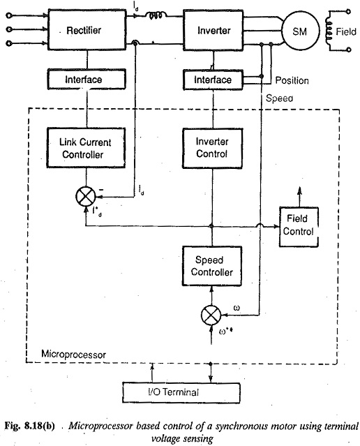
The Inverter Control using Terminal Voltage Sensing of the synchronous motor is obtained using the triggering pulses to the inverter which are synchronized with the rotor position. These signals are obtained by processing the phase reference signals P1,P2,P3 and a high frequency signal S4 obtained from a shaft encoder. This shaft encoder is a mechanical device fitted to the motor shaft. It therefore impairs the mechanical ruggedness of the system. The shaft encoder can be dispensed with, if the synchronizing of the trigger pulses with rotor position is accomplished by sensing the stator voltages. The thyristors can be triggered with minimum turn off angle to avail of the advantages of higher torque and improved power factor. The method can be implemented on a microprocessor used to perform the functions of monitoring and control. The Inverter Control using Terminal Voltage Sensing configuration and characteristics are supported by the necessary software, as described in the foregoing, so that the control strategies are adaptable to modifications without making any changes in the hardware. The only difference between the foregoing implementation of the microprocessor and the present one is the sensing of voltages in place of a rotor position sensor to provide the phase reference signals for determining the delay of firing and speed signal, which is also used as a firing signal.
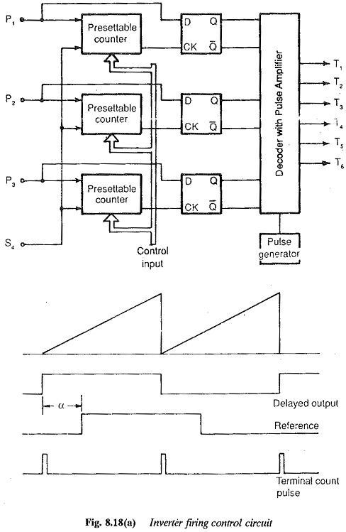
Similar to the case of rotor position sensing (Fig. 8.17), signals identical to phase reference signals P1,P2,P3 are obtained by detecting the zero crossings of the voltages (Fig. 8.18). The polarity of Inverter Control using Terminal Voltage Sensing between two phases is obtained. A frequency multiplier (Fig. 8.18) is used to obtain the high frequency signal S4, similar to that obtained with a shaft encoder. The purpose of this signal is to provide the necessary delay angle in firing the thyristor so that the armature current has a definite phase difference with respect to the phase voltage, as well as to provide the information about the speed. The multiplication involved decides the resolution of firing angle. The signals P1,P2,P3 and S4 are processed in the same way as has been described in the previous is section dealing with the shaft encoder.
However Inverter Control using Terminal Voltage Sensing is not possible at standstill. The forced commutation routine must be involved to start the motor. A pair of thyristors addressed by the CPU are fired so that maximum torque in the required direction
is developed. The pair of thyristors can be identified by measuring the induced voltages of the armature at the instant of applying the field voltage. The Inverter Control using Terminal Voltage Sensing depend upon the rotor position. The sign of the highest voltage is determined. This information is accessed and processed to identify the correct pair of thyristors to be fired. The starting process using forced commutation is implemented until the rotor accelerates to the speed at which natural commutation takes over.