Linear integrated circuits and applications | Op Amp Basics:
Linear integrated circuits and applications – The term IC means integrated circuit where all the components are fabricated on the same chip. Most of the ICs are produced by the monolithic process. In this process, all the active Elements like transistors and all the passive elements like resistances, capacitances are fabricated on a single piece of Semiconductor Material, generally silicon. This is called silicon.wafer or a substrate. Such a monolithic process makes low cost mass production of ICs possible.
With the help of ICs the circuit design becomes very simple. The variety of useful circuits can be built without the necessity of knowing about the complex internal circuitry.
The various advantages of Linear integrated circuits and applications are,
- Small size : Practically size of an IC is thousands of times smaller than the discrete circuit.
- Low cost : Thousands of silicon wafers consisting of number of components individually, are produced simultaneously, called mass production. Due to this, cost of IC is very very low and hence millions of ICs are now in use, annually.
- Less weight : Number of components are fabricated on a single silicon wafer hence weight of IC is very much less compared to a discrete circuit consisting of same number of components.
- Low supply voltages : ICs work at lower voltages which avoids the need of the large supply voltages.
- Low power consumption : The power consumption of ICs is very very low.
- Highly reliable : Due to absence of soldered connections and less interconnections, the ICs are highly reliable from the performance point of view. Due to low power consumption, the temperature rise of ICs is also low which further increases the reliability, accuracy and the life of ICs.
In addition to these important advantages, the ICs are used popularly because of versatility, flexibility and dependability.
Op Amp Basics:
The operational amplifier, most commonly referred as ‘op-amp’ was introduced in 1940s. The first operational amplifier was designed in 1948 using vacuum tubes. In those days, it was used in the analog computers to perform a variety of mathematical operations such as addition, subtraction, multiplication etc. Due to its use in performing mathematical operations it has been given a name operational amplifier. Due to the use of vacuum tubes, the early op-amps were bulky, power consuming and expensive.
Robert J. Widlar at Fairchild brought out the popular 741 integrated circuit (IC) op-amp between 1964 to 1968. The IC version of op-amp uses BJTs and FETs which are fabricated along with the other supporting components, on a single semiconductor chip or wafer which is of a pinhead size. With the help of IC op-amp, the circuit design becomes very simple. The variety of useful circuits can be built without the necessity of knowing about the complex internal circuitry. Moreover, IC op-amps are inexpensive, take up less space and consume less power. The IC op-amp has become an integral part of almost every electronic circuit which uses Linear integrated circuits and applications. The modern linear IC op-amp works at lower voltages. It is so low in cost that millions are now in use, annually. Because of their low cost, small size, versatility, flexibility, and dependability, op-amps are used in the fields of process control, communications, computers, power and signal sources, displays and measuring systems. The op-amp is basically an excellent high gain d.c. amplifier.
Op Amp Symbol and Terminals:
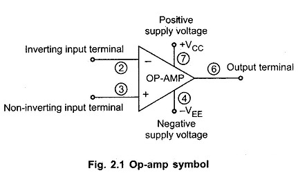
The symbol for an op-amp along with its various terminals, is shown in the Fig. 2.1
The op-amp is indicated basically by a triangle which points in the direction of the signal flow.
All the op-amps have at least following five terminals
- The positive supply voltage terminal VCC or + V.
- The negative supply voltage terminal – VEE or – V.
- The output terminal.
- The inverting input terminal, marked as negative.
- The noninverting input terminal, marked as positive.
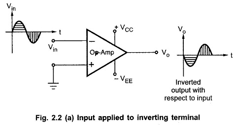
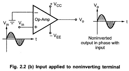
The input at inverting input terminal results in opposite polarity (antiphase) output. While the input at noninverting input terminal results in the same polarity (phase) output. This is shown in the Fig. 2.2(a) and (b). The input and output are in antiphase means having 180° phase difference in between them while inphase input and output means having 0° phase difference in between them.
The op-amp is fabricated on a tiny silicon chip and packaged in a suitable case. Fine gauge wires are used to connect the chip to the external leads.
Power Supply for Op Amps:
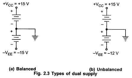
The op-amp works on a dual supply. A dual supply consists of two supply voltages both d.c., whose middle point is generally the ground terminal.
The dual supply is generally balanced i.e. the voltages of the positive supply +Vcc and that of the negative supply -VEE are same in magnitude. The typical commercially used power supply voltages are ± 15 V. But if the two voltage magnitudes are not same in a dual supply it is called as unbalanced dual supply. The balanced and unbalanced types of dual supply are shown in the Below Fig 2.3 (a) and (b) respectively.
Practically in most of the op-amp circuits balanced dual supply is used. The other popular balanced dual supply voltages are ± 9 V, ± 12 V, ± 22 V etc.


