Internal Architecture of 8086:
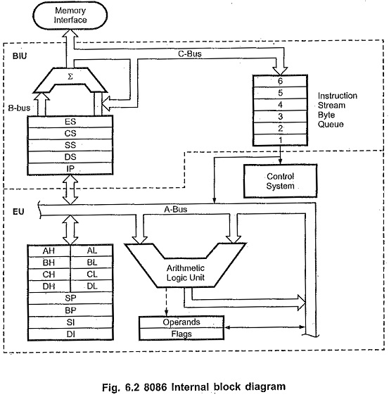
Fig. 6.2 shows a block diagram of Internal Architecture of 8086. It is internally divided into two separate functional units. These are the Bus Interface Unit (BIU) and the Execution Unit (EU). These two functional units can work simultaneously to increase system speed and hence the throughput. Throughput is a measure of number of instructions executed per unit time.
Bus Interface Unit:
The bus interface unit is the Internal Architecture of 8086 to the outside world. It provides a full 16-bit bi-directional data bus and 20-bit address bus. The bus interface unit is responsible for performing all external bus operations, as listed below.
Functions of Bus Interface Unit
- It sends address of the memory or I/O.
- It fetches instruction from memory.
- It reads data from port/memory.
- It Writes data into port/memory.
- It supports instruction queuing.
- It provides the address relocation facility.
To implement these functions the BIU contains the instruction queue, segment registers instruction pointer, address summer and bus control logic.
Instruction Queue:
To speed up program execution, the BIU fetches six instruction bytes ahead of time from the memory. These prefetched instruction bytes are held for the execution unit in a group of registers called Queue. With the help of queue it is possible to fetch next instruction when current instruction is in execution. For example, current instruction in execution is a multiplication instruction. In Internal Architecture of 8086, operands for multiplication operations are within registers. Still it requires 100 clock cycles to execute multiply instruction. Like multiplication there are number of other instructions in 3086 which need a quite a large number- of clock cycles for execution. During this execution time the BIU fetches the next instruction or instructions from memory into the instruction queue instead of remaining idle. The BIU continues this process as long as the queue is not full. Due to this, execution unit gets the ready instruction in the queue and instruction fetch time is eliminated. This is illustrated in Fig. 6.3.
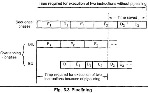
The queue operates on the principle first in first out (FIFO). So that the execution unit gets the instructions for execution in the order they are fetched. In case of JUMP and CALL instructions, instruction already fetched in queue are of no use. Hence, in these cases queue is dumped and newly formed by loading instructions from new address specified by JUMP or CALL instruction. Feature of fetching the next instruction while the current instruction is executing is called pipelining.
Segment Registers:
The physical address of the Internal Architecture of 8086 is 20-bits wide to access 1 Mbyte memory locations. However, its registers and memory locations which contain logical addresses are just 16-bits wide. Hence 8086 uses memory segmentation. It treats the 1 Mbyte of memory as divided into segments, with a maximum size of a segment as 64 Kbytes. Thus any location within the segment can be accessed using 16 bits. The Internal Architecture of 8086 allows only four active segments at a time, as shown in the Fig. 6.4. For the selection of the four active segments the 16-bit segment registers are provided within the BIU of the 8086. These four registers are :
Code segment (CS) register, the data segment (DS) register, the stack segment (SS) register, and the extra segment (ES) register. These are used to hold the upper 16-bits of the starting addresses of the four memory segments, on which 8086 works at a particular time. For example, the value in CS identifies the starting address of 64 K-byte segment known as code segment. By “starting address“, we mean the lowest addressed byte in the active code segment. The starting address is also known as base address or segment base.
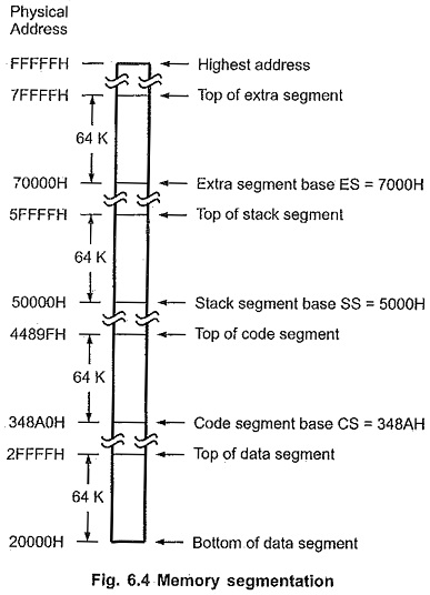
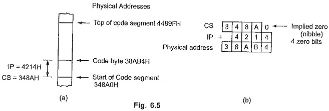
The BIT) always inserts zeros for the lowest 4 bits (nibble) in the contents of segment register to generate 20-bit base address. For example, if the code segment register contains 348AH, then code segment will start at address 348A0H.
Functions of Segment Registers:
- The CS register holds the upper 16-bits of the starting address of the segment from which the BIU is currently fetching the instruction code byte.
- The SS register is used for the upper 16-bits of the starting address for the program stack (all stack related instructions will operate on stack)
- ES register and DS register are used to hold the upper 16-bits of the starting address of the two memory segments Which are used for data.
Rules For Memory Segmentation:
- The four segments can overlap for small programs. In a minimum system all four segments can start at the address 00000H.
- The segment can begin/start at any memory address which is divisible by 16.
Advantages of Memory Segmentation:
- It allows the memory addressing capacity to be 1 Mbyte even though the address associated with individual instruction is only 16-bit.
- It allows instruction code, data, stack, and portion of program to be more than 64 KB long by using more than one code, data, stack segment, and extra
- It facilitates use of separate memory areas for program, data and stack.
- It permits a program or its data to be put in different areas of memory, each time the program is executed i.e. program can be relocated which is very useful in multiprogramming.
Instruction Pointer:
The instruction pointer register holds the 16-bit address of the next Code byte within the code segment. The value contained in the IP is referred to as an offset. This value must be offset from (added to) the segment base address in CS to produce the required 20-bit physical address.
Generation of 20-bit Address:
The contents of the CS register are multiplied by 16 i.e. shifted by 4 position to the left by inserting 4 zero bits and then the offset i.e. the contents of IP register are added to the shifted contents of CS to generate physical address. As shown in the Fig 6.5, the contents of CS register are 348AH, therefore the shifted contents of CS register are 348A0H. When the BIU adds the offset of 4214H in the IP to this starting address, the result is 20-bit physical of 38AB4H.
Execution Unit [EU]:
The execution unit of Internal Architecture of 8086 tells the BIU from where to fetch instructions or data, decodes instructions and executes instructions. It contains
- Control Circuitry
- Instruction Decoder
- Arithmetic Logic Unit (ALU)
- Flag Register
- General Purpose Registers
- Pointers and Index Registers
Control Circuitry, Instruction Decoder, ALU:
The control circuitry in the EU directs the internal operations. A decoder in the EU translates the instructions fetched from memory into a series of actions wlifeh the EU performs. ALU is 16-bit. It can add, subtract, AND, OR, XOR, increment, decrements, complement and shift binary numbers.
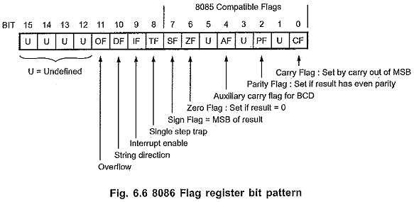
Flag Register:
A flag is a flip–flop which indicates some condition produced by the execution of an instruction or controls certain operations of the EU. The flag register contains nine active flags as shown in the Fig. 6.6.
General Purpose Registers:
The EU has. 8 general purpose registers labeled ATI, AL, BH, BL, CH, CL, DH, and DL. These registers can be used individually for temporary storage of 8 bit data. The AL register is also called accumulator. Certain pairs of these general purpose registers can be used together to store 16-bit data, such as AX, BX, CX and DX.
Pointers and Index Registers:
All segment registers are 16-bit. But it is necessary to put 20-bit address (physical address) on the address bus. To get 20-bit physical address one more register is associated with each segment register the way IP is associated with CS.
These additional registers belong to the pointer and index group. The pointer and index group consists of instruction pointer (IP), stack pointer (SP), BP (base pointer), source index (SI) and destination index (DI) registers.
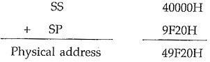
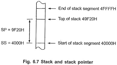
Stack Pointer (SP) : The stack pointer (SP) register contains the 16-bit offset from the start of the segment to the top of stack. For stack operation, physical address is produced by adding the contents of stack pointer register to the segment base address in SS. To do this the contents of the stack segment register are shifted four bits left and the contents of SP are added to the shifted result. If the contents of SP are 9F20H and SS are 4000H then the physical address is calculated as follows. (Refer Fig. 6.7)
SS = 4000H after shifting four bits left SS = 40000H
Now
Base Pointer, Source Index and Destination Index (BP, SI and DI)
These three 16-bit registers can be used as general purpose registers. However, their . main use is to hold the 16-bit offset of the data word in one of the segments.
Base pointer : We can use the BP register instead of SP for accessing the stack using the based addressing. mode. In this case, the 20-bit physical stack address. is calculated from BP and SS. Addressing modes are discussed in later section.
Source Index : Source index (SI) can be used to hold the offset of a data word in the data segment. In this case, the 20-bit physical data address is calculated from SI and
Destination Index : The ES register .points to the extra segment in which data is stored. String instructions always use ES and DI to determined the 20-bit physical address for the destination.
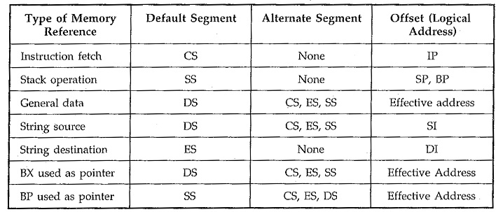
Default and Alternate Register Assignments:
Table 6.1 shows that some memory references and their default and alternate segment definitions. For example, instruction codes can only be stored in the code segment with IP used as an offset. Similarly, for stack operations only SS and SP or BP registers can be used to give segment and offset addresses respectively. On the other hand, for accessing general data, string source; data pointed by BX and BP registers; it is possible to use alternate segments by using segment override prefix. See examples given after Table 6.1.
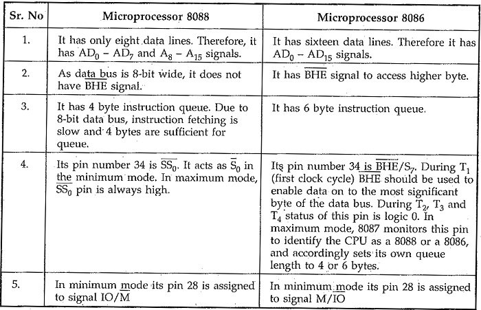
Comparison between 8086 and 8088:
It is important to note that differences between 8088 and 8086 are only in their BIU and not in EU. The execution unit (EU) is the same for both. As EU is same, the programming instructions are exactly the same for each. Programs written for the 8086 can be run on the 8088 without any changes.